MIRROR OUTER MIRROR SWITCH INSPECTION
PROCEDURE

 84870A
1.INSPECT OUTER MIRROR SWITCH ASSEMBLY (w/ Retract Mirror)
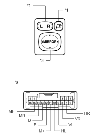
The L position of the left/right adjustment switch: Measure the resistance of the mirror switch. (for LHD)
| *1 | Retract Switch |
| *2 | Left/Right Adjustment Switch |
| *3 | Mirror Switch |
| *a | Component without harness connected
(Outer Mirror Switch Assembly) |
- Standard resistance (for left side):
Tester Connection Switch Condition Specified Condition 9 (VL) - 13 (B)
11 (M+) - 12 (E)UP Below 1 Ω OFF 10 kΩ or higher 9 (VL) - 12 (E)
11 (M+) - 13 (B)DOWN Below 1 Ω OFF 10 kΩ or higher 10 (HL) - 13 (B)
11 (M+) - 12 (E)LEFT Below 1 Ω OFF 10 kΩ or higher 10 (HL) - 12 (E)
11 (M+) - 13 (B)RIGHT Below 1 Ω OFF 10 kΩ or higher
If the result is not as specified, replace the switch assembly.
The R position of the left/right adjustment switch: Measure the resistance of the mirror switch.
- Standard resistance (for right side):
Tester Connection Switch Condition Specified Condition 8 (VR) - 13 (B)
11 (M+) - 12 (E)UP Below 1 Ω OFF 10 kΩ or higher 8 (VR) - 12 (E)
11 (M+) - 13 (B)DOWN Below 1 Ω OFF 10 kΩ or higher 7 (HR) - 13 (B)
11 (M+) - 12 (E)LEFT Below 1 Ω OFF 10 kΩ or higher 7 (HR) - 12 (E)
11 (M+) - 13 (B)RIGHT Below 1 Ω OFF 10 kΩ or higher
If the result is not as specified, replace the switch assembly.
Measure the resistance of the retract switch.
- OK:
Tester Connection Switch Condition Specified Condition 15 (MF) - 13 (B)
14 (MR) - 12 (E)RETURN Below 1 Ω 15 (MF) - 12 (E)
14 (MR) - 13 (B)RETRACT Below 1 Ω
If the result is not as specified, replace the switch.
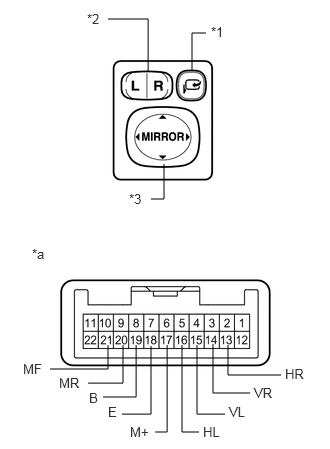
The L position of the left/right adjustment switch: Measure the resistance of the mirror switch. (for RHD)
| *1 | Retract Switch |
| *2 | Left/Right Adjustment Switch |
| *3 | Mirror Switch |
| *a | Component without harness connected
(Outer Mirror Switch Assembly) |
- Standard resistance (for left side):
Tester Connection Switch Condition Specified Condition 15 (VL) - 19 (B)
17 (M+) - 18 (E)UP Below 1 Ω OFF 10 kΩ or higher 15 (VL) - 18 (E)
17 (M+) - 19 (B)DOWN Below 1 Ω OFF 10 kΩ or higher 16 (HL) - 19 (B)
17 (M+) - 18 (E)LEFT Below 1 Ω OFF 10 kΩ or higher 16 (HL) - 18 (E)
17 (M+) - 19 (B)RIGHT Below 1 Ω OFF 10 kΩ or higher
If the result is not as specified, replace the switch assembly.
The R position of the left/right adjustment switch: Measure the resistance of the mirror switch.
- Standard resistance (for right side):
Tester Connection Switch Condition Specified Condition 14 (VR) - 19 (B)
17 (M+) - 18 (E)UP Below 1 Ω OFF 10 kΩ or higher 14 (VR) - 18 (E)
17 (M+) - 19 (B)DOWN Below 1 Ω OFF 10 kΩ or higher 13 (HR) - 19 (B)
17 (M+) - 18 (E)LEFT Below 1 Ω OFF 10 kΩ or higher 13 (HR) - 18 (E)
17 (M+) - 19 (B)RIGHT Below 1 Ω OFF 10 kΩ or higher
If the result is not as specified, replace the switch assembly.
Measure the resistance of the retract switch.
- OK:
Tester Connection Switch Condition Specified Condition 21 (MF) - 19 (B)
20 (MR) - 18 (E)RETURN Below 1 Ω 21 (MF) - 18 (E)
20 (MR) - 19 (B)RETRACT Below 1 Ω
If the result is not as specified, replace the switch.
84870A
2.INSPECT OUTER MIRROR SWITCH ASSEMBLY (w/o Retract Mirror)
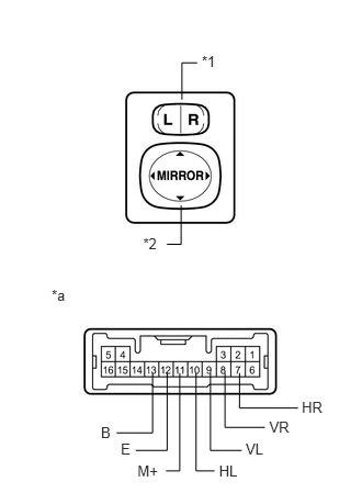
The L position of the left/right adjustment switch: Measure the resistance of the mirror switch. (for LHD)
| *1 | Left/Right Adjustment Switch |
| *2 | Mirror Switch |
| *a | Component without harness connected
(Outer Mirror Switch Assembly) |
- Standard resistance (for left side):
Tester Connection Switch Condition Specified Condition 9 (VL) - 13 (B)
11 (M+) - 12 (E)UP Below 1 Ω OFF 10 kΩ or higher 9 (VL) - 12 (E)
11 (M+) - 13 (B)DOWN Below 1 Ω OFF 10 kΩ or higher 10 (HL) - 13 (B)
11 (M+) - 12 (E)LEFT Below 1 Ω OFF 10 kΩ or higher 10 (HL) - 12 (E)
11 (M+) - 13 (B)RIGHT Below 1 Ω OFF 10 kΩ or higher
If the result is not as specified, replace the switch assembly.
The R position of the left/right adjustment switch: Measure the resistance of the mirror switch.
- Standard resistance (for right side):
Tester Connection Switch Condition Specified Condition 8 (VR) - 13 (B)
11 (M+) - 12 (E)UP Below 1 Ω OFF 10 kΩ or higher 8 (VR) - 12 (E)
11 (M+) - 13 (B)DOWN Below 1 Ω OFF 10 kΩ or higher 7 (HR) - 13 (B)
11 (M+) - 12 (E)LEFT Below 1 Ω OFF 10 kΩ or higher 7 (HR) - 12 (E)
11 (M+) - 13 (B)RIGHT Below 1 Ω OFF 10 kΩ or higher
If the result is not as specified, replace the switch assembly.
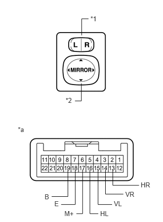
The L position of the left/right adjustment switch: Measure the resistance of the mirror switch. (for RHD)
| *1 | Left/Right Adjustment Switch |
| *2 | Mirror Switch |
| *a | Component without harness connected
(Outer Mirror Switch Assembly) |
- Standard resistance (for left side):
Tester Connection Switch Condition Specified Condition 15 (VL) - 19 (B)
17 (M+) - 18 (E)UP Below 1 Ω OFF 10 kΩ or higher 15 (VL) - 18 (E)
17 (M+) - 19 (B)DOWN Below 1 Ω OFF 10 kΩ or higher 16 (HL) - 19 (B)
17 (M+) - 18 (E)LEFT Below 1 Ω OFF 10 kΩ or higher 16 (HL) - 18 (E)
17 (M+) - 19 (B)RIGHT Below 1 Ω OFF 10 kΩ or higher
If the result is not as specified, replace the switch assembly.
The R position of the left/right adjustment switch: Measure the resistance of the mirror switch.
- Standard resistance (for right side):
Tester Connection Switch Condition Specified Condition 14 (VR) - 19 (B)
17 (M+) - 18 (E)UP Below 1 Ω OFF 10 kΩ or higher 14 (VR) - 18 (E)
17 (M+) - 19 (B)DOWN Below 1 Ω OFF 10 kΩ or higher 13 (HR) - 19 (B)
17 (M+) - 18 (E)LEFT Below 1 Ω OFF 10 kΩ or higher 13 (HR) - 18 (E)
17 (M+) - 19 (B)RIGHT Below 1 Ω OFF 10 kΩ or higher
If the result is not as specified, replace the switch assembly.