Home › Vehicle Interior › SLIDING ROOF › SLIDING ROOF SYSTEM
RM24M0E _58 Vehicle Interior _059597 SLIDING ROOF _0292254 SLIDING ROOF SYSTEM J

SLIDING ROOF  SLIDING ROOF SYSTEM  Sliding Roof Control Switch Circuit  


DESCRIPTION

·

Power slide door control switch (Front sliding roof control switch) circuit:

This circuit detects the state of the power slide door control switch (front sliding roof control switch) and sends it to the sliding roof drive gear (rear sunshade control ECU).

·

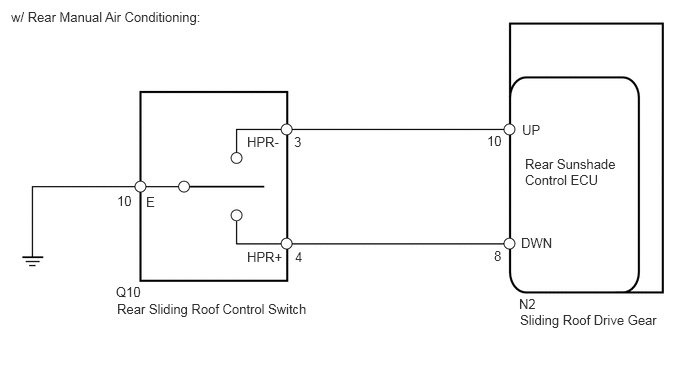
Rear sliding roof control switch circuit:

This circuit detects the state of the rear sliding roof control switch and sends it to the sliding roof drive gear (rear sunshade control ECU).


WIRING DIAGRAM

Power Slide Door Control Switch (Front Sliding Roof Control Switch) Circuit
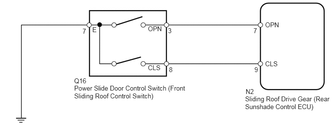

B143784E05
1.583,1.802 3.99,2.281 2.406,0.479 10 false Power Slide Door Control Switch (Front Sliding Roof Control Switch) 1.583,1.646 1.885,1.792 0.302,0.146 10 false Q16 3.604,1.406 3.813,1.604 0.208,0.198 10 false 8 3.583,0.573 3.729,0.771 0.146,0.198 10 false 3 5.427,1.406 5.635,1.604 0.208,0.198 10 false 9 5.406,0.573 5.552,0.771 0.146,0.198 10 false 7 5.656,1.281 6.031,1.438 0.375,0.156 10 false CLS 3.156,0.531 3.531,0.688 0.375,0.156 10 false OPN 3.156,1.365 3.531,1.521 0.375,0.156 10 false CLS 5.656,0.448 6.031,0.604 0.375,0.156 10 false OPN 1.969,0.552 2.115,0.719 0.146,0.167 10 false E 1.76,0.583 1.917,0.74 0.156,0.156 10 false 7 5.229,2.031 7.01,2.448 1.781,0.417 10 false Sliding Roof Drive Gear (Rear Sunshade Control ECU) 5.24,1.875 5.458,2.021 0.219,0.146 10 false N2


Rear Sliding Roof Control Switch Circuit
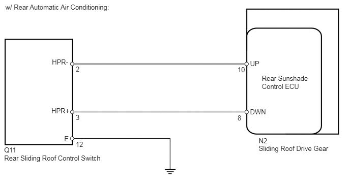

B144253E01
5.298,2.955 6.827,3.097 1.529,0.142 10 Sliding Roof Drive Gear 5.298,2.801 6.827,2.943 1.529,0.142 10 N2 5.362,1.526 6.364,1.847 1.002,0.321 10 Rear Sunshade Control ECU 5.12,1.222 5.914,1.413 0.795,0.191 10 UP 5.12,2.206 5.914,2.397 0.795,0.191 10 DWN 0.086,3.156 2.159,3.304 2.073,0.149 10 Rear Sliding Roof Control Switch 0.086,2.994 2.159,3.143 2.073,0.149 10 Q11 1.064,1.191 1.451,1.371 0.387,0.180 10 HPR- 1.053,2.185 1.469,2.355 0.416,0.170 10 HPR+ 1.551,2.322 1.783,2.492 0.232,0.170 10 3 1.315,2.76 1.731,2.930 0.416,0.170 10 E 0.11,0.064 2.717,0.215 2.607,0.151 10 w/ Rear Automatic Air Conditioning: 1.551,2.873 1.783,3.043 0.232,0.170 10 12 4.864,1.348 5.096,1.518 0.232,0.170 10 10 4.864,2.336 5.096,2.506 0.232,0.170 10 8 1.551,1.334 1.783,1.504 0.232,0.170 10 2

B143217E11
5.417,3.25 6.927,3.427 1.51,0.177 10 false Sliding Roof Drive Gear 5.469,1.625 6.49,1.938 1.021,0.313 10 false Rear Sunshade Control ECU 5.438,1.271 6.229,1.458 0.792,0.188 10 false UP 5.427,2.448 6.219,2.635 0.792,0.188 10 false DWN 1.219,3.135 3.375,3.302 2.156,0.167 10 false Rear Sliding Roof Control Switch 2.573,1.396 2.958,1.573 0.385,0.177 10 false HPR- 2.573,2.594 2.99,2.76 0.417,0.167 10 false HPR+ 1.521,2.021 1.76,2.198 0.24,0.177 10 false E 0.115,0.094 2.51,0.333 2.396,0.24 10 false w/ Rear Manual Air Conditioning: 1.208,2.958 1.521,3.104 0.313,0.146 10 false Q10 3.063,1.396 3.26,1.615 0.198,0.219 10 false 3 3.073,2.594 3.25,2.781 0.177,0.188 10 false 4 1.219,2.01 1.49,2.167 0.271,0.156 10 false 10 5.073,1.385 5.333,1.573 0.26,0.188 10 false 10 5.146,2.583 5.354,2.771 0.208,0.188 10 false 8 5.406,3.083 5.698,3.24 0.292,0.156 10 false N2


PROCEDURE

1.CHECK SLIDING ROOF OPERATION
a.

Check the operation of the sliding roof using the power slide door control switch (front sliding roof control switch) and rear sliding roof control switch.

Result:
Result Proceed to
Sliding roof does not operate using power slide door control switch (front sliding roof control switch) A
Sliding roof does not operate using rear sliding roof control switch B


A

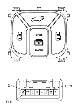
2.INSPECT POWER SLIDE DOOR CONTROL SWITCH (FRONT SLIDING ROOF CONTROL SWITCH)

B

4.CHECK VEHICLE CONDITION
2.INSPECT POWER SLIDE DOOR CONTROL SWITCH (FRONT SLIDING ROOF CONTROL SWITCH)
B135700E02
2.87,3.706 3.211,3.850 0.341,0.144 10 OPN 0.268,4.403 0.568,4.547 0.299,0.144 10 CLS 0.34,3.688 0.468,3.830 0.128,0.142 10 E 0.608,4.476 1.012,4.164 false 0.499,3.776 1.178,4.033 false 2.054,3.999 2.849,3.784 false

a.

Remove the map light.


b.

Measure the resistance of the switch.

Standard resistance:
Tester Connection Switch Condition Specified Condition
3 (OPN) - 7 (E) Front sliding roof control switch is OPEN Below 1 Ω
8 (CLS) - 7 (E) Front sliding roof control switch is CLOSE Below 1 Ω
3 (OPN) - 7 (E)
8 (CLS) - 7 (E)
Front sliding roof control switch is OFF 10 kΩ or higher


OK

3.CHECK WIRE HARNESS (POWER SLIDE DOOR CONTROL SWITCH - SLIDING ROOF DRIVE GEAR AND BODY GROUND)

NG

REPLACE POWER SLIDE DOOR CONTROL SWITCH (FRONT SLIDING ROOF CONTROL SWITCH)

3.CHECK WIRE HARNESS (POWER SLIDE DOOR CONTROL SWITCH - SLIDING ROOF DRIVE GEAR AND BODY GROUND)
a.

Disconnect the Q16 switch connector.


b.

Disconnect the N2 gear connector.


c.

Measure the resistance of the wire harness side connectors.

Standard resistance:
Tester Connection Specified Condition
Q16-3 (OPN) - N2-7 (OPN) Below 1 Ω
Q16-8 (CLS) - N2-9 (CLS) Below 1 Ω
Q16-7 (E) - Body ground Below 1 Ω
Q16-3 (OPN) - Body ground 10 kΩ or higher
Q16-8 (CLS) - Body ground 10 kΩ or higher


OK

PROCEED TO NEXT INSPECTION PROCEDURE SHOWN IN PROBLEM SYMPTOMS TABLE

NG

REPAIR OR REPLACE HARNESS OR CONNECTOR

4.CHECK VEHICLE CONDITION
a.

Check the vehicle condition.

Result:
Result Proceed to
w/ Rear automatic air conditioner A
w/ Rear manual air conditioner B


A

5.INSPECT REAR AIR CONDITIONING CONTROL PANEL (REAR SLIDING ROOF CONTROL SWITCH)

B

7.INSPECT REAR COOLER SWITCH (REAR SLIDING ROOF CONTROL SWITCH)
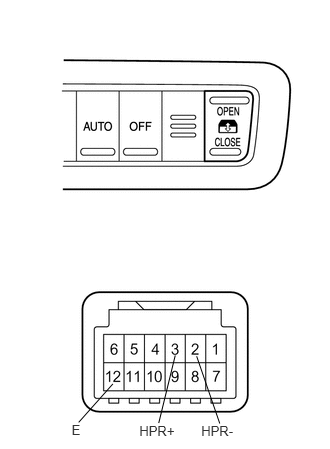
5.INSPECT REAR AIR CONDITIONING CONTROL PANEL (REAR SLIDING ROOF CONTROL SWITCH)
a.
B146491E01
0.746,4.399 0.894,4.566 0.148,0.167 10 E 1.451,4.406 1.861,4.553 0.410,0.146 10 HPR+ 2.096,4.411 2.506,4.557 0.410,0.146 10 HPR- 0.819,4.399 1.176,3.998 false 1.825,3.702 1.653,4.406 false 2.048,3.71 2.289,4.411 false

Remove the rear air conditioning control panel.


b.

Measure the resistance of the switch.

Standard resistance:
Tester Connection Switch Condition Specified Condition
3 (HPR+) - 12 (E) Rear sliding roof control switch is OPEN Below 1 Ω
2 (HPR-) - 12 (E) Rear sliding roof control switch is CLOSE Below 1 Ω
2 (HPR-) - 12 (E)
3 (HPR+) - 12 (E)
Rear sliding roof control switch is OFF 10 kΩ or higher


OK

6.CHECK WIRE HARNESS (REAR AIR CONDITIONING CONTROL PANEL - SLIDING ROOF DRIVE GEAR)

NG

REPLACE REAR AIR CONDITIONING CONTROL PANEL (REAR SLIDING ROOF CONTROL SWITCH)

6.CHECK WIRE HARNESS (REAR AIR CONDITIONING CONTROL PANEL - SLIDING ROOF DRIVE GEAR)
a.

Disconnect the Q11 switch connector.


b.

Disconnect the N2 drive gear connector.


c.

Measure the resistance of the wire harness side connectors.

Standard resistance:
Tester Connection Specified Condition
Q11-3 (HPR+) - N2-8 (DWN) Below 1 Ω
Q11-2 (HPR-) - N2-10 (UP) Below 1 Ω
Q11-12 (E) - Body ground Below 1 Ω
Q11-2 (HPR-) - Body ground 10 kΩ or higher
Q11-3 (HPR+) - Body ground 10 kΩ or higher


OK

PROCEED TO NEXT CIRCUIT INSPECTION SHOWN IN PROBLEM SYMPTOMS TABLE

NG

REPAIR OR REPLACE HARNESS OR CONNECTOR

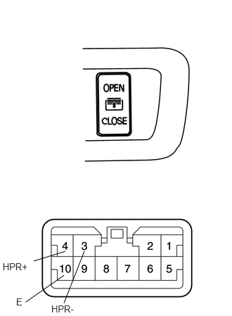
7.INSPECT REAR COOLER SWITCH (REAR SLIDING ROOF CONTROL SWITCH)
a.
B135699E03
0.76,4.487 1.169,4.626 0.408,0.140 10 HPR- 0.039,3.862 0.447,4.002 0.408,0.140 10 HPR+ 0.239,4.389 0.387,4.537 0.148,0.148 10 E 0.497,3.864 0.967,3.719 false 1.25,3.716 0.947,4.487 false 0.382,4.47 0.949,4.074 false

Remove the rear cooler switch.


b.

Measure the resistance of the switch.

Standard resistance:
Tester Connection Switch Condition Specified Condition
3 (HPR-) - 10 (E) Rear sliding roof control switch is OPEN Below 1 Ω
4 (HPR+) - 10 (E) Rear sliding roof control switch is CLOSE Below 1 Ω
4 (HPR+) - 10 (E)
3 (HPR-) - 10 (E)
Rear sliding roof control switch is OFF 10 kΩ or higher


OK

8.CHECK WIRE HARNESS (REAR COOLER SWITCH - SLIDING ROOF DRIVE GEAR AND BODY GROUND)

NG

REPLACE REAR COOLER SWITCH (REAR SLIDING ROOF CONTROL SWITCH)

8.CHECK WIRE HARNESS (REAR COOLER SWITCH - SLIDING ROOF DRIVE GEAR AND BODY GROUND)
a.

Disconnect the Q10 switch connector.


b.

Disconnect the N2 drive gear connector.


c.

Measure the resistance of the wire harness side connectors.

Standard resistance:
Tester Connection Specified Condition
Q10-4 (HPR+) - N2-8 (DWN) Below 1 Ω
Q10-3 (HPR-) - N2-10 (UP) Below 1 Ω
Q10-10 (E) - Body ground Below 1 Ω
Q10-3 (HPR-) - Body ground 10 kΩ or higher
Q10-4 (HPR+) - Body ground 10 kΩ or higher


OK

PROCEED TO NEXT CIRCUIT INSPECTION SHOWN IN PROBLEM SYMPTOMS TABLE

NG

REPAIR OR REPLACE HARNESS OR CONNECTOR