CAN COMMUNICATION CAN COMMUNICATION SYSTEM TERMINALS OF ECU
- NOTICE:
- ·
Turn the engine switch off before measuring the resistances of the main wire and the branch wire.
·Before measuring the resistance, leave the vehicle for at least 1 minute and do not operate the engine switch, any switches or doors. If doors need to be opened in order to check connectors, open the doors and leave them open.
- HINT:
-
Operating the engine switch, any switches or any doors triggers related ECU and sensor communication with the CAN, which causes resistance variation.
JUNCTION CONNECTOR (for LHD)
No. 1 Junction Connector
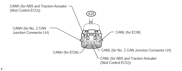
| No. 1 Junction Connector | Wiring Color | Connect to |
|---|---|---|
| CANH (A29-1) | B | ABS and traction actuator (skid control ECU) |
| CANL (A29-5) | W | ABS and traction actuator (skid control ECU) |
| CANH (A29-4) | B | ECM |
| CANL (A29-7) | W | ECM |
| CANH (A29-3) | B | No. 2 CAN junction connector LH |
| CANL (A29-6) | W | No. 2 CAN junction connector LH |
No. 2 CAN Junction Connector LH
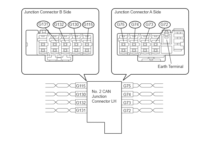
| Junction Connector A Side | Color (CANH Side) | Color (CANL Side) |
|---|---|---|
| Steering angle sensor (G72) | BR | W |
| No. 1 CAN junction connector RH (G73) | B | W |
| No. 1 junction connector (G74) | L | W |
| Main body ECU (G75) | B | W |
| Junction Connector B Side | Color (CANH Side) | Color (CANL Side) |
|---|---|---|
| DLC3 (G131) | GR | W |
| Center airbag sensor assembly (G132) | Y | W |
| Power steering ECU (G130) | Y | W |
| Navigation receiver assembly* (G115) | BR | W |
*: w/ Navigation System
- HINT:
- ·
The connectors connected to the junction connector can be distinguished by the colors of the bus lines and the connecting side of the connector.
·The connectors can be connected to any terminals on the same side.
No. 1 CAN Junction Connector RH
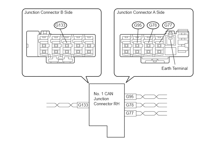
| Junction Connector A Side | Color (CANH Side) | Color (CANL Side) |
|---|---|---|
| Air conditioning amplifier (G77) | V | W |
| No. 2 CAN junction connector LH (G78) | B | W |
| AFS ECU* (G95) | Y | SB |
*: w/ AFS
| Junction Connector B Side | Color (CANH Side) | Color (CANL Side) |
|---|---|---|
| No. 2 junction connector (G133) | L | W |
- HINT:
- ·
The connectors connected to the junction connector can be distinguished by the colors of the bus lines and the connecting side of the connector.
·The connectors can be connected to any terminals on the same side.
No. 2 Junction Connector
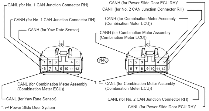
| Junction Connector | Wiring Color | Connect to |
|---|---|---|
| CANH (N48-1) | B | No. 1 CAN junction connector RH |
| CANL (N48-6) | W | No. 1 CAN junction connector RH |
| CANH (N48-2) | B | Yaw rate sensor |
| CANL (N48-7) | W | Yaw rate sensor |
| CANH (N48-3) | B | Combination meter assembly (combination meter ECU) |
| CANL (N48-8) | W | Combination meter assembly (combination meter ECU) |
| CANH (N48-5) | B | No. 2 CAN junction connector RH |
| CANL (N48-10) | W | No. 2 CAN junction connector RH |
| CANH (N48-12) | B | Power slide door ECU RH* |
| CANL (N48-11) | W | Power slide door ECU RH* |
| CANH (N48-4) | B | Combination meter assembly (combination meter ECU) |
| CANL (N48-9) | W | Combination meter assembly (combination meter ECU) |
*: w/ Power Slide Door System
No. 3 Junction Connector
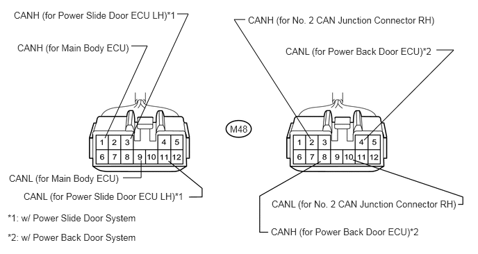
| Junction Connector | Wiring Color | Connect to |
|---|---|---|
| CANH (M48-1) | B | Main body ECU |
| CANL (M48-9) | W | Main body ECU |
| CANH (M48-3) | B | Power slide door ECU LH*1 |
| CANL (M48-11) | W | Power slide door ECU LH*1 |
| CANH (M48-8) | B | Power back door ECU*2 |
| CANL (M48-4) | W | Power back door ECU*2 |
| CANH (M48-2) | B | No. 2 CAN junction connector RH |
| CANL (M48-10) | W | No. 2 CAN junction connector RH |
*1: w/ Power Slide Door System
*2: w/ Power Back Door System
No. 2 CAN Junction Connector RH
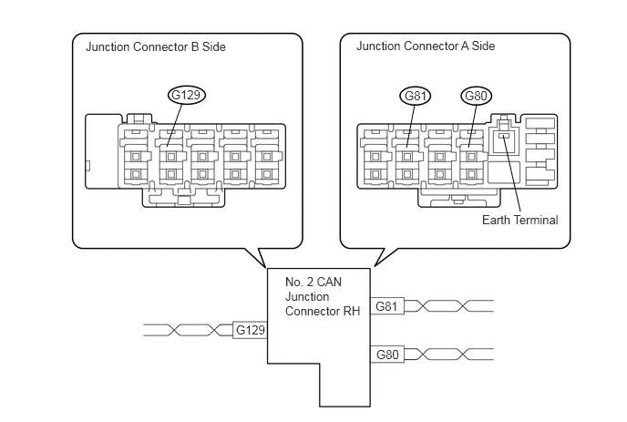
| Junction Connector A Side | Color (CANH Side) | Color (CANL Side) |
|---|---|---|
| Certification ECU (G80) | SB | W |
| No. 3 junction connector (G81) | R | W |
| Junction Connector B Side | Color (CANH Side) | Color (CANL Side) |
|---|---|---|
| No. 2 junction connector (G129) | V | W |
- HINT:
- ·
The connectors connected to the junction connector can be distinguished by the colors of the bus lines and the connecting side of the connector.
·The connectors can be connected to any terminals on the same side.
JUNCTION CONNECTOR (for RHD)
No. 2 CAN Junction Connector LH
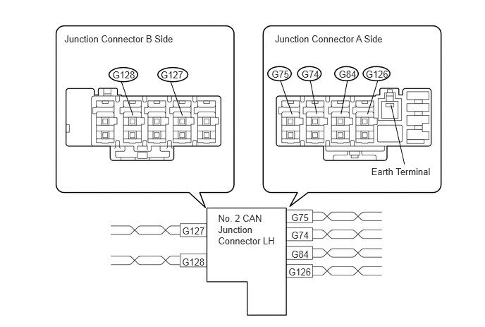
| Junction Connector A Side | Color (CANH Side) | Color (CANL Side) |
|---|---|---|
| AFS ECU* (G126) | Y | SB |
| ABS and traction actuator (skid control ECU) (G84) | BR | W |
| ECM (G74) | L | W |
| Main body ECU (G75) | B | W |
*: w/ AFS
| Junction Connector B Side | Color (CANH Side) | Color (CANL Side) |
|---|---|---|
| Air conditioning amplifier (G128) | V | W |
| No. 5 junction connector (G127) | B | W |
- HINT:
- ·
The connectors connected to the junction connector can be distinguished by the colors of the bus lines and the connecting side of the connector.
·The connectors can be connected to any terminals on the same side.
No. 5 Junction Connector
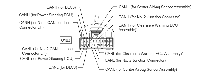
| Junction Connector | Wiring Color | Connect to |
|---|---|---|
| CANH (G103-1) | B | No. 2 CAN junction connector LH |
| CANL (G103-12) | W | No. 2 CAN junction connector LH |
| CANH (G103-2) | Y | Power steering ECU |
| CANL (G103-13) | W | Power steering ECU |
| CANH (G103-3) | GR | DLC3 |
| CANL (G103-14) | W | DLC3 |
| CANH (G103-4) | Y | Center airbag sensor assembly |
| CANL (G103-15) | W | Center airbag sensor assembly |
| CANH (G103-5) | B | No. 2 junction connector |
| CANL (G103-16) | W | No. 2 junction connector |
| CANH (G103-6) | B | Clearance warning ECU assembly* |
| CANL (G103-17) | W | Clearance warning ECU assembly* |
*: w/ Toyota Parking Assist-sensor System
No. 2 Junction Connector
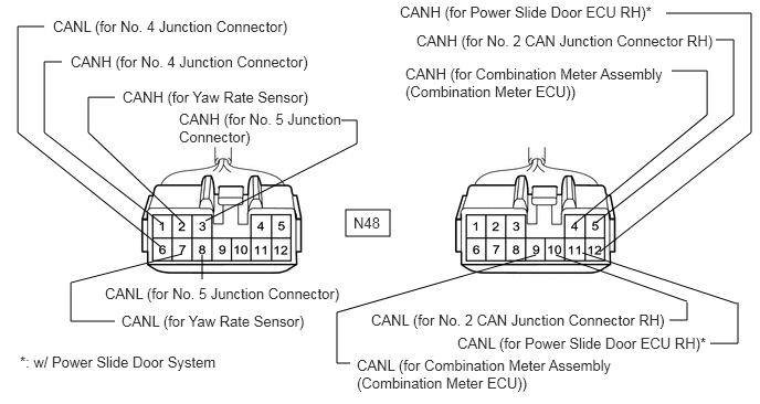
| Junction Connector | Wiring Color | Connect to |
|---|---|---|
| CANH (N48-1) | B | No. 4 junction connector |
| CANL (N48-6) | W | No. 4 junction connector |
| CANH (N48-2) | B | Yaw rate sensor |
| CANL (N48-7) | W | Yaw rate sensor |
| CANH (N48-3) | B | No. 5 junction connector |
| CANL (N48-8) | W | No. 5 junction connector |
| CANH (N48-5) | B | No. 2 CAN junction connector RH |
| CANL (N48-10) | W | No. 2 CAN junction connector RH |
| CANH (N48-12) | B | Power slide door ECU RH* |
| CANL (N48-11) | W | Power slide door ECU RH* |
| CANH (N48-4) | B | Combination meter assembly (combination meter ECU) |
| CANL (N48-9) | W | Combination meter assembly (combination meter ECU) |
*: w/ Power Slide Door System
No. 4 Junction Connector
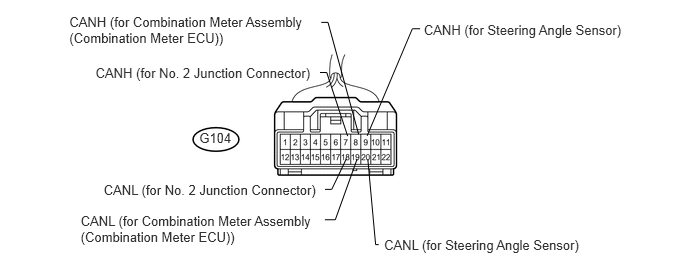
| Junction Connector | Wiring Color | Connect to |
|---|---|---|
| CANH (G104-7) | B | No. 2 junction connector |
| CANL (G104-18) | W | No. 2 junction connector |
| CANH (G104-8) | B | Combination meter assembly (combination meter ECU) |
| CANL (G104-19) | W | Combination meter assembly (combination meter ECU) |
| CANH (G104-9) | BR | Steering angle sensor |
| CANL (G104-20) | W | Steering angle sensor |
No. 3 Junction Connector
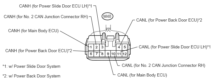
| Junction Connector | Wiring Color | Connect to |
|---|---|---|
| CANH (M48-1) | B | Main body ECU |
| CANL (M48-9) | W | Main body ECU |
| CANH (M48-2) | B | No. 2 CAN junction connector RH |
| CANL (M48-10) | W | No. 2 CAN junction connector RH |
| CANH (M48-3) | B | Power slide door ECU LH*1 |
| CANL (M48-11) | W | Power slide door ECU LH*1 |
| CANH (M48-8) | B | Power back door ECU*2 |
| CANL (M48-4) | W | Power back door ECU*2 |
*1: w/ Power Slide Door System
*2: w/ Power Back Door System
No. 2 CAN Junction Connector RH
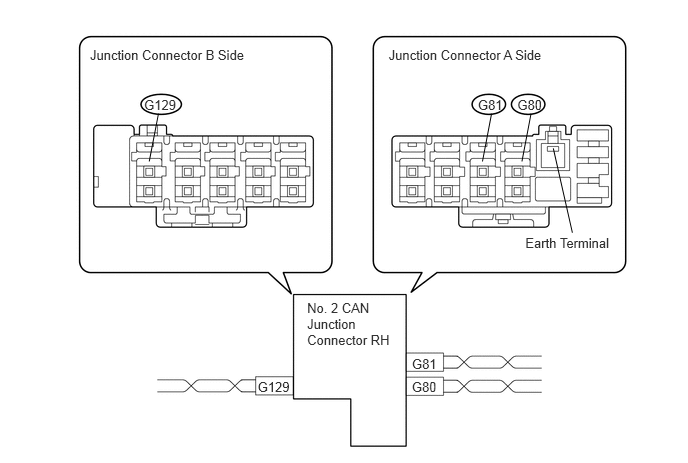
| Junction Connector A Side | Color (CANH Side) | Color (CANL Side) |
|---|---|---|
| Certification ECU (G80) | SB | W |
| No. 3 junction connector (G81) | R | W |
| Junction Connector B Side | Color (CANH Side) | Color (CANL Side) |
|---|---|---|
| No. 2 junction connector (G129) | V | W |
- HINT:
- ·
The connectors connected to the junction connector can be distinguished by the colors of the bus lines and the connecting side of the connector.
·The connectors can be connected to any terminals on the same side.
TERMINALS OF CONNECTORS FOR JUNCTION CONNECTOR (NO. 2 CAN JUNCTION CONNECTOR LH, NO. 1 CAN JUNCTION CONNECTOR RH*, NO. 2 CAN JUNCTION CONNECTOR RH)
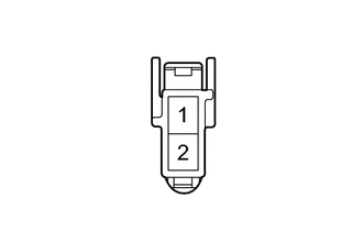
| Terminal | Terminal Symbol |
|---|---|
| 1 | CANH |
| 2 | CANL |
*: for LHD
CHECK DLC3
Disconnect the cable from the negative (-) battery terminal.
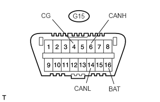
Measure the resistance of the connector.
| Symbols (Terminal No.) | Wiring Color | Condition | Specified Condition |
|---|---|---|---|
| CANH (G15-6) - CANL (G15-14) | GR - W | Cable disconnected from negative (-) battery terminal | 54 to 69 Ω |
| CANH (G15-6) - CG (G15-4) | GR - W-B | Cable disconnected from negative (-) battery terminal | 200 Ω or higher |
| CANL (G15-14) - CG (G15-4) | W - W-B | Cable disconnected from negative (-) battery terminal | 200 Ω or higher |
| CANH (G15-6) - BAT (G15-16) | GR - L | Cable disconnected from negative (-) battery terminal | 6 kΩ or higher |
| CANL (G15-14) - BAT (G15-16) | W - L | Cable disconnected from negative (-) battery terminal | 6 kΩ or higher |
CHECK ABS AND TRACTION ACTUATOR (SKID CONTROL ECU)
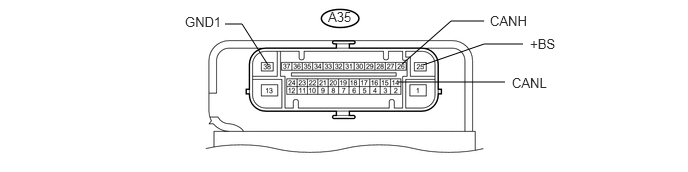
Disconnect the cable from the negative (-) battery terminal.
Disconnect the A35 ABS and traction actuator assembly (skid control ECU) connector.
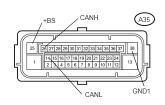
Measure the resistance of the wire harness side connector.
| Symbols (Terminal No.) | Wiring Color | Condition | Specified Condition |
|---|---|---|---|
| CANH (A35-26) - CANL (A35-14) | B - W | Cable disconnected from negative (-) battery terminal | 54 to 69 Ω |
| CANH (A35-26) - GND1 (A35-38) | B - W-B | Cable disconnected from negative (-) battery terminal | 200 Ω or higher |
| CANL (A35-14) - GND1 (A35-38) | W - W-B | Cable disconnected from negative (-) battery terminal | 200 Ω or higher |
| CANH (A35-26) - +BS (A35-25) | B - W | Cable disconnected from negative (-) battery terminal | 6 kΩ or higher |
| CANL (A35-14) - +BS (A35-25) | W - W | Cable disconnected from negative (-) battery terminal | 6 kΩ or higher |
CHECK STEERING ANGLE SENSOR
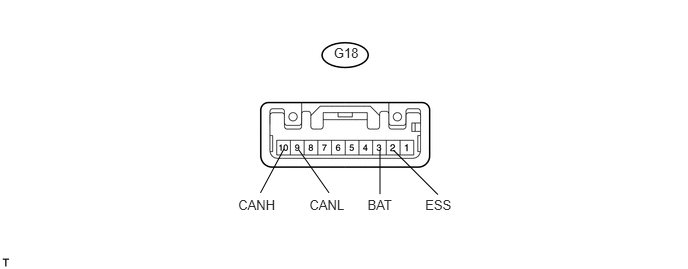
Disconnect the cable from the negative (-) battery terminal.
Disconnect the G18 steering angle sensor connector.
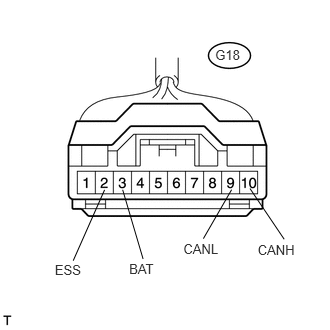
Measure the resistance of the wire harness side connector.
| Symbols (Terminal No.) | Wiring Color | Condition | Specified Condition |
|---|---|---|---|
| CANH (G18-10) - CANL (G18-9) | BR - W | Cable disconnected from negative (-) battery terminal | 54 to 69 Ω |
| CANH (G18-10) - ESS (G18-2) | BR - W-B | Cable disconnected from negative (-) battery terminal | 200 Ω or higher |
| CANL (G18-9) - ESS (G18-2) | W - W-B | Cable disconnected from negative (-) battery terminal | 200 Ω or higher |
| CANH (G18-10) - BAT (G18-3) | BR - W | Cable disconnected from negative (-) battery terminal | 6 kΩ or higher |
| CANL (G18-9) - BAT (G18-3) | W - W | Cable disconnected from negative (-) battery terminal | 6 kΩ or higher |
CHECK YAW RATE SENSOR
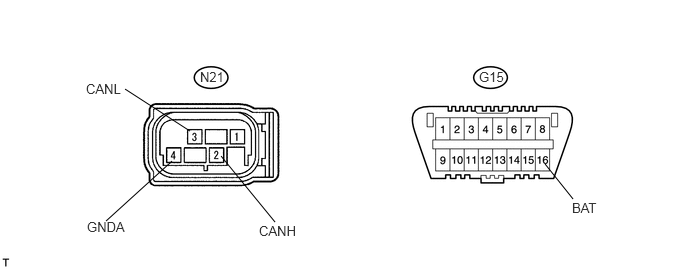
Disconnect the cable from the negative (-) battery terminal.
Disconnect the N21 yaw rate sensor connector.
Measure the resistance of the wire harness side connector.
| Symbols (Terminal No.) | Wiring Color | Condition | Specified Condition |
|---|---|---|---|
| CANH (N21-2) - CANL (N21-3) | B - W | Cable disconnected from negative (-) battery terminal | 54 to 69 Ω |
| CANH (N21-2) - GNDA (N21-4) | B - W-B | Cable disconnected from negative (-) battery terminal | 200 Ω or higher |
| CANL (N21-3) - GNDA (N21-4) | W - W-B | Cable disconnected from negative (-) battery terminal | 200 Ω or higher |
| CANH (N21-2) - BAT (G15-16) | B - L | Cable disconnected from negative (-) battery terminal | 6 kΩ or higher |
| CANL (N21-3) - BAT (G15-16) | W - L | Cable disconnected from negative (-) battery terminal | 6 kΩ or higher |
CHECK AIR CONDITIONING AMPLIFIER
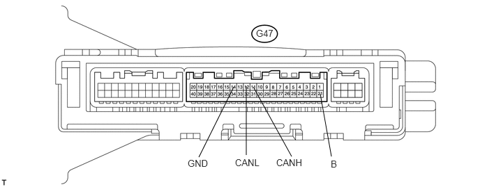
Disconnect the cable from the negative (-) battery terminal.
Disconnect the G47 air conditioning amplifier connector.
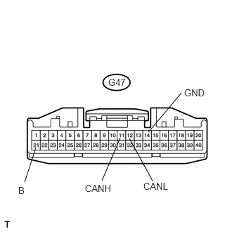
Measure the resistance of the wire harness side connector.
| Symbols (Terminal No.) | Wiring Color | Condition | Specified Condition |
|---|---|---|---|
| CANH (G47-11) - CANL (G47-12) | V - W | Cable disconnected from negative (-) battery terminal | 54 to 69 Ω |
| CANH (G47-11) - GND (G47-14) | V - W-B | Cable disconnected from negative (-) battery terminal | 200 Ω or higher |
| CANL (G47-12) - GND (G47-14) | W - W-B | Cable disconnected from negative (-) battery terminal | 200 Ω or higher |
| CANH (G47-11) - B (G47-21) | V - W | Cable disconnected from negative (-) battery terminal | 6 kΩ or higher |
| CANL (G47-12) - B (G47-21) | W - W | Cable disconnected from negative (-) battery terminal | 6 kΩ or higher |
CHECK ECM (for 2AZ-FE)
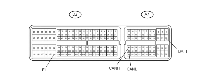
Disconnect the cable from the negative (-) battery terminal.
Disconnect the A7 and D2 ECM connectors.
Measure the resistance of the wire harness side connector.
| Symbols (Terminal No.) | Wiring Color | Condition | Specified Condition |
|---|---|---|---|
| CANH (A7-41) - CANL (A7-49) | B - W | Cable disconnected from negative (-) battery terminal | 108 to 132 Ω |
| CANH (A7-41) - E1 (D2-104) | B - BR | Cable disconnected from negative (-) battery terminal | 200 Ω or higher |
| CANL (A7-49) - E1 (D2-104) | W - BR | Cable disconnected from negative (-) battery terminal | 200 Ω or higher |
| CANH (A7-41) - BATT (A7-20) | B - W | Cable disconnected from negative (-) battery terminal | 6 kΩ or higher |
| CANL (A7-49) - BATT (A7-20) | W - W | Cable disconnected from negative (-) battery terminal | 6 kΩ or higher |
CHECK ECM (for 2GR-FE)
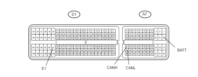
Disconnect the cable from the negative (-) battery terminal.
Disconnect the A7 and D1 ECM connectors.
Measure the resistance of the wire harness side connector.
| Symbols (Terminal No.) | Wiring Color | Condition | Specified Condition |
|---|---|---|---|
| CANH (A7-41) - CANL (A7-49) | B - W | Cable disconnected from negative (-) battery terminal | 108 to 132 Ω |
| CANH (A7-41) - E1 (D1-81) | B - BR | Cable disconnected from negative (-) battery terminal | 200 Ω or higher |
| CANL (A7-49) - E1 (D1-81) | W - BR | Cable disconnected from negative (-) battery terminal | 200 Ω or higher |
| CANH (A7-41) - BATT (A7-20) | B - W | Cable disconnected from negative (-) battery terminal | 6 kΩ or higher |
| CANL (A7-49) - BATT (A7-20) | W - W | Cable disconnected from negative (-) battery terminal | 6 kΩ or higher |
CHECK CENTER AIRBAG SENSOR ASSEMBLY
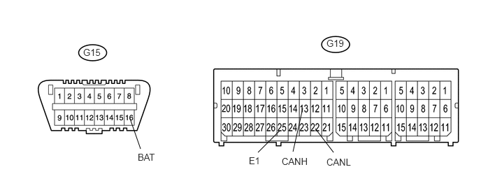
Disconnect the cable from the negative (-) battery terminal.
Disconnect the G19 center airbag sensor assembly connector.
Measure the resistance of the wire harness side connector.
| Symbols (Terminal No.) | Wiring Color | Condition | Specified Condition |
|---|---|---|---|
| CANH (G19-13) - CANL (G19-22) | Y - W | Cable disconnected from negative (-) battery terminal | 54 to 69 Ω |
| CANH (G19-13) - E1 (G19-25) | Y - W-B | Cable disconnected from negative (-) battery terminal | 200 Ω or higher |
| CANL (G19-22) - E1 (G19-25) | W - W-B | Cable disconnected from negative (-) battery terminal | 200 Ω or higher |
| CANH (G19-13) - BAT (G15-16) | Y - L | Cable disconnected from negative (-) battery terminal | 6 kΩ or higher |
| CANL (G19-22) - BAT (G15-16) | W - L | Cable disconnected from negative (-) battery terminal | 6 kΩ or higher |
CHECK POWER STEERING ECU
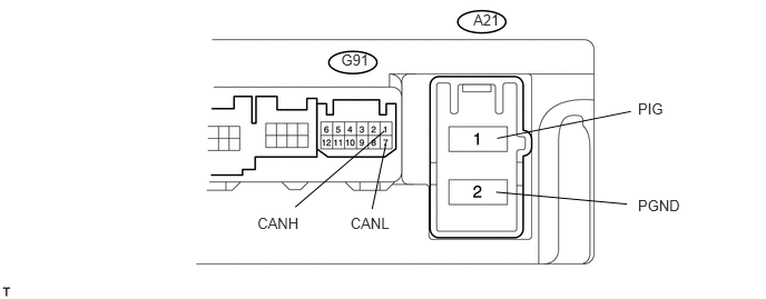
Disconnect the cable from the negative (-) battery terminal.
Disconnect the A21 and G91 power steering ECU connectors.
Measure the resistance of the wire harness side connector.
| Symbols (Terminal No.) | Wiring Color | Condition | Specified Condition |
|---|---|---|---|
| CANH (G91-1) - CANL (G91-7) | Y - W | Cable disconnected from negative (-) battery terminal | 54 to 69 Ω |
| CANH (G91-1) - PGND (A21-2) | Y - W | Cable disconnected from negative (-) battery terminal | 200 Ω or higher |
| CANL (G91-7) - PGND (A21-2) | W - W | Cable disconnected from negative (-) battery terminal | 200 Ω or higher |
| CANH (G91-1) - PIG (A21-1) | Y - B | Cable disconnected from negative (-) battery terminal | 6 kΩ or higher |
| CANL (G91-7) - PIG (A21-1) | W - B | Cable disconnected from negative (-) battery terminal | 6 kΩ or higher |
CHECK COMBINATION METER ASSEMBLY (COMBINATION METER ECU)
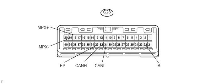
Disconnect the cable from the negative (-) battery terminal.
Disconnect the G28 combination meter assembly (combination meter ECU) connector.
Measure the resistance of the wire harness side connector.
| Symbols (Terminal No.) | Wiring Color | Condition | Specified Condition |
|---|---|---|---|
| CANH (G28-32) - CANL (G28-31) | B - W | Cable disconnected from negative (-) battery terminal | 108 to 132 Ω |
| CANH (G28-32) - EP (G28-33) | B - BR | Cable disconnected from negative (-) battery terminal | 200 Ω or higher |
| CANL (G28-31) - EP (G28-33) | W - BR | Cable disconnected from negative (-) battery terminal | 200 Ω or higher |
| CANH (G28-32) - B (G28-22) | B - W | Cable disconnected from negative (-) battery terminal | 6 kΩ or higher |
| CANL (G28-31) - B (G28-22) | W - W | Cable disconnected from negative (-) battery terminal | 6 kΩ or higher |
| MPX+ (G28-18) - MPX- (G28-19) | LG - W | Cable disconnected from negative (-) battery terminal | 108 to 132 Ω |
| MPX+ (G28-18) - EP (G28-33) | LG - BR | Cable disconnected from negative (-) battery terminal | 200 Ω or higher |
| MPX- (G28-19) - EP (G28-33) | W - BR | Cable disconnected from negative (-) battery terminal | 200 Ω or higher |
| MPX+ (G28-18) - B (G28-22) | LG - W | Cable disconnected from negative (-) battery terminal | 6 kΩ or higher |
| MPX- (G28-19) - B (G28-22) | W - W | Cable disconnected from negative (-) battery terminal | 6 kΩ or higher |
CHECK MAIN BODY ECU (INSTRUMENT PANEL JUNCTION BLOCK LH)
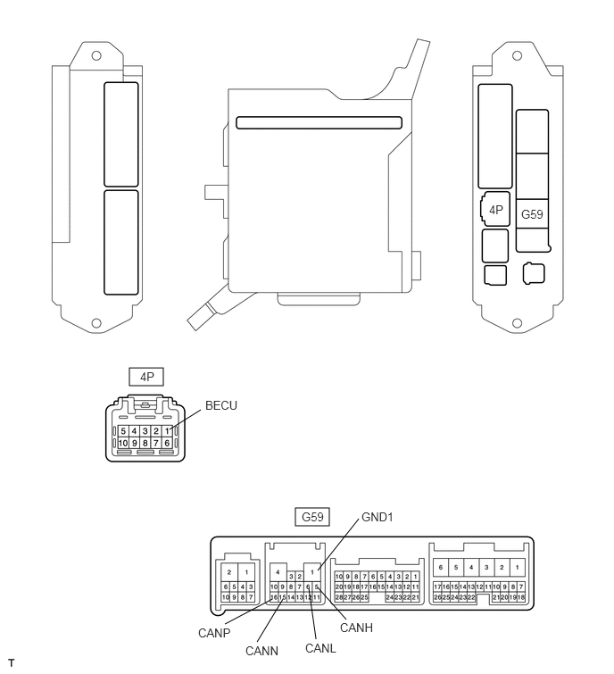
Disconnect the cable from the negative (-) battery terminal.
Disconnect the G59 and 4P main body ECU (instrument panel junction block LH) connectors.
Measure the resistance of the wire harness side connector.
| Symbols (Terminal No.) | Wiring Color | Condition | Specified Condition |
|---|---|---|---|
| CANH (G59-5) - CANL (G59-6) | B - W | Cable disconnected from negative (-) battery terminal | 54 to 69 Ω |
| CANH (G59-5) - GND1 (G59-1) | B - W-B | Cable disconnected from negative (-) battery terminal | 200 Ω or higher |
| CANL (G59-6) - GND1 (G59-1) | W - W-B | Cable disconnected from negative (-) battery terminal | 200 Ω or higher |
| CANH (G59-5) - BECU (4P-1) | B - R | Cable disconnected from negative (-) battery terminal | 6 kΩ or higher |
| CANL (G59-6) - BECU (4P-1) | W - R | Cable disconnected from negative (-) battery terminal | 6 kΩ or higher |
| CANP (G59-16) - CANN (G59-15) | B - W | Cable disconnected from negative (-) battery terminal | 108 to 132 Ω |
| CANP (G59-16) - GND1 (G59-1) | B - W-B | Cable disconnected from negative (-) battery terminal | 200 Ω or higher |
| CANN (G59-15) - GND1 (G59-1) | W - W-B | Cable disconnected from negative (-) battery terminal | 200 Ω or higher |
| CANP (G59-16) - BECU (4P-1) | B - R | Cable disconnected from negative (-) battery terminal | 6 kΩ or higher |
| CANN (G59-15) - BECU (4P-1) | W - R | Cable disconnected from negative (-) battery terminal | 6 kΩ or higher |
CHECK AFS ECU
- HINT:
-
For vehicles with AFS only.
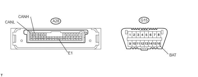
Disconnect the cable from the negative (-) battery terminal.
Disconnect the A28 AFS ECU connector.
Measure the resistance of the wire harness side connector.
| Symbols (Terminal No.) | Wiring Color | Condition | Specified Condition |
|---|---|---|---|
| CANH (A28-12) - CANL (A28-13) | B - W | Cable disconnected from negative (-) battery terminal | 54 to 69 Ω |
| CANH (A28-12) - E1 (A28-22) | B - W-B | Cable disconnected from negative (-) battery terminal | 200 Ω or higher |
| CANL (A28-13) - E1 (A28-22) | W - W-B | Cable disconnected from negative (-) battery terminal | 200 Ω or higher |
| CANH (A28-12) - BAT (G15-16) | B - L | Cable disconnected from negative (-) battery terminal | 6 kΩ or higher |
| CANL (A28-13) - BAT (G15-16) | W - L | Cable disconnected from negative (-) battery terminal | 6 kΩ or higher |
CHECK NAVIGATION RECEIVER ASSEMBLY
- HINT:
-
For vehicles with navigation system only.
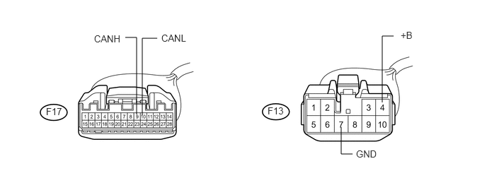
Disconnect the cable from the negative (-) battery terminal.
Disconnect the F17 and F13 navigation receiver assembly connectors.
Measure the resistance of the wire harness side connector.
| Symbols (Terminal No.) | Wiring Color | Condition | Specified Condition |
|---|---|---|---|
| CANH (F17-9) - CANL (F17-10) | SB - W | Cable disconnected from negative (-) battery terminal | 54 to 69 Ω |
| CANH (F17-9) - GND (F13-7) | SB - BR | Cable disconnected from negative (-) battery terminal | 200 Ω or higher |
| CANL (F17-10) - GND (F13-7) | W - BR | Cable disconnected from negative (-) battery terminal | 200 Ω or higher |
| CANH (F17-9) - +B (F13-4) | SB - Y | Cable disconnected from negative (-) battery terminal | 6 kΩ or higher |
| CANL (F17-10) - +B (F13-4) | W - Y | Cable disconnected from negative (-) battery terminal | 6 kΩ or higher |
CHECK POWER SLIDE DOOR ECU LH
- HINT:
-
For vehicles with power slide door system only.
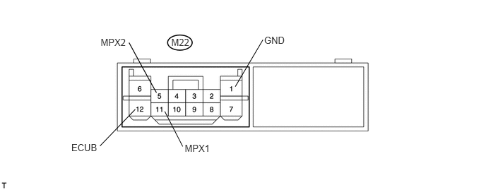
Disconnect the cable from the negative (-) battery terminal.
Disconnect the M22 power slide door ECU LH connector.
Measure the resistance of the wire harness side connector.
| Symbols (Terminal No.) | Wiring Color | Condition | Specified Condition |
|---|---|---|---|
| MPX1 (M22-11) - MPX2 (M22-5) | B - W | Cable disconnected from negative (-) battery terminal | 54 to 69 Ω |
| MPX1 (M22-11) - GND (M22-1) | B - W-B | Cable disconnected from negative (-) battery terminal | 200 Ω or higher |
| MPX2 (M22-5) - GND (M22-1) | W - W-B | Cable disconnected from negative (-) battery terminal | 200 Ω or higher |
| MPX1 (M22-11) - ECUB (M22-12) | B - R | Cable disconnected from negative (-) battery terminal | 6 kΩ or higher |
| MPX2 (M22-5) - ECUB (M22-12) | W - R | Cable disconnected from negative (-) battery terminal | 6 kΩ or higher |
CHECK POWER SLIDE DOOR ECU RH
- HINT:
-
For vehicles with power slide door system only.
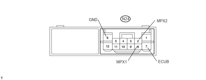
Disconnect the cable from the negative (-) battery terminal.
Disconnect the N24 power slide door ECU RH connector.
Measure the resistance of the wire harness side connector.
| Symbols (Terminal No.) | Wiring Color | Condition | Specified Condition |
|---|---|---|---|
| MPX1 (N24-8) - MPX2 (N24-2) | B - W | Cable disconnected from negative (-) battery terminal | 54 to 69 Ω |
| MPX1 (N24-8) - GND (N24-6) | B - W-B | Cable disconnected from negative (-) battery terminal | 200 Ω or higher |
| MPX2 (N24-2) - GND (N24-6) | W - W-B | Cable disconnected from negative (-) battery terminal | 200 Ω or higher |
| MPX1 (N24-8) - ECUB (N24-7) | B - LG | Cable disconnected from negative (-) battery terminal | 6 kΩ or higher |
| MPX2 (N24-2) - ECUB (N24-7) | W - LG | Cable disconnected from negative (-) battery terminal | 6 kΩ or higher |
CHECK POWER BACK DOOR ECU
- HINT:
-
For vehicles with power back door system only.
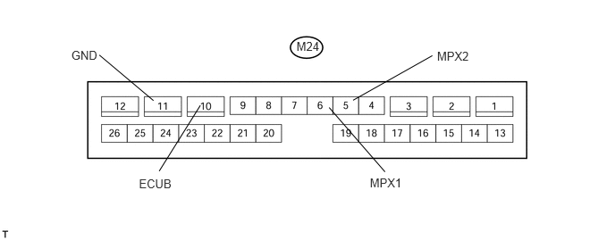
Disconnect the cable from the negative (-) battery terminal.
Disconnect the M24 power back door ECU connector.
Measure the resistance of the wire harness side connector.
| Symbols (Terminal No.) | Wiring Color | Condition | Specified Condition |
|---|---|---|---|
| MPX1 (M24-6) - MPX2 (M24-5) | B - W | Cable disconnected from negative (-) battery terminal | 54 to 69 Ω |
| MPX1 (M24-6) - GND (M24-11) | B - W-B | Cable disconnected from negative (-) battery terminal | 200 Ω or higher |
| MPX2 (M24-5) - GND (M24-11) | W - W-B | Cable disconnected from negative (-) battery terminal | 200 Ω or higher |
| MPX1 (M24-6) - ECUB (M24-10) | B - R | Cable disconnected from negative (-) battery terminal | 6 kΩ or higher |
| MPX2 (M24-5) - ECUB (M24-10) | W - R | Cable disconnected from negative (-) battery terminal | 6 kΩ or higher |
CHECK CERTIFICATION ECU
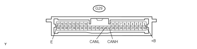
Disconnect the cable from the negative (-) battery terminal.
Disconnect the G29 certification ECU connector.
Measure the resistance of the wire harness side connector.
| Symbols (Terminal No.) | Wiring Color | Condition | Specified Condition |
|---|---|---|---|
| CANH (G29-27) - CANL (G29-28) | SB - W | Cable disconnected from negative (-) battery terminal | 54 to 69 Ω |
| CANH (G29-27) - E (G29-17) | SB- W-B | Cable disconnected from negative (-) battery terminal | 200 Ω or higher |
| CANL (G29-28) - E (G29-17) | W - W-B | Cable disconnected from negative (-) battery terminal | 200 Ω or higher |
| CANH (G29-27) - +B (G29-1) | SB - BE | Cable disconnected from negative (-) battery terminal | 6 kΩ or higher |
| CANL (G29-28) - +B (G29-1) | W - BE | Cable disconnected from negative (-) battery terminal | 6 kΩ or higher |
CHECK CLEARANCE WARNING ECU ASSEMBLY
- HINT:
-
For vehicles with Toyota parking assist-sensor system only.
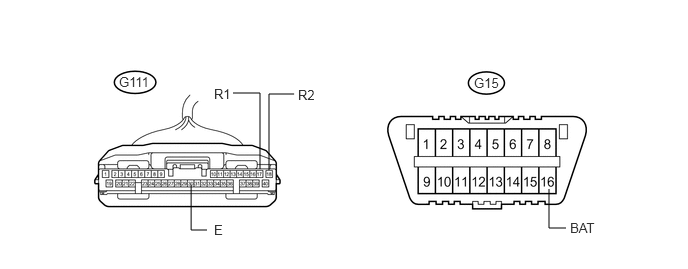
Disconnect the cable from the negative (-) battery terminal.
Disconnect the G111 clearance warning ECU assembly connector.
Measure the resistance of the wire harness side connector.
| Symbols (Terminal No.) | Wiring Color | Condition | Specified Condition |
|---|---|---|---|
| R1 (G111-17) - R2 (G111-18) | B - W | Cable disconnected from negative (-) battery terminal | 54 to 69 Ω |
| R1 (G111-17) - E (G111-30) | B - W-B | Cable disconnected from negative (-) battery terminal | 200 Ω or higher |
| R2 (G111-18) - E (G111-30) | W - W-B | Cable disconnected from negative (-) battery terminal | 200 Ω or higher |
| R1 (G111-17) - BAT (G15-16) | B - L | Cable disconnected from negative (-) battery terminal | 6 kΩ or higher |
| R2 (G111-18) - BAT (G15-16) | W - L | Cable disconnected from negative (-) battery terminal | 6 kΩ or higher |