Home › Power Source / Network › CAN COMMUNICATION › CAN COMMUNICATION SYSTEM › 2014.09–2016.05
RM24M0E _57 Power Source / Network _059598 CAN COMMUNICATION _0292257 CAN COMMUNICATION SYSTEM J

CAN COMMUNICATION  CAN COMMUNICATION SYSTEM  Check CAN Bus Line for Short to GND (RHD Models)  


DESCRIPTION

There may be a short circuit between the CAN bus line and GND when there is resistance between terminals 6 (CANH) and 4 (CG) or terminals 14 (CANL) and 4 (CG) of the DLC3.

Symptom Trouble Area
There is low resistance between terminals 6 (CANH) and 4 (CG) or terminals 14 (CANL) and 4 (CG) of DLC3.
·

Short to GND

·

Brake actuator assembly (skid control ECU)*1

·

ABS and traction actuator (skid control ECU)*2

·

Power steering ECU

·

Steering angle sensor*3

·

Yaw rate sensor*2

·

ECM

·

Center airbag sensor assembly

·

Air conditioning amplifier

·

Combination meter assembly (Combination meter ECU)

·

Instrument panel junction block (Main body ECU)

·

Network gateway ECU

·

No. 2 CAN junction connector LH

·

No. 2 junction connector

·

No. 4 junction connector

·

No. 5 junction connector


*1: w/o VSC

*2: w/ VSC

*3: w/ VSC or w/ AFS

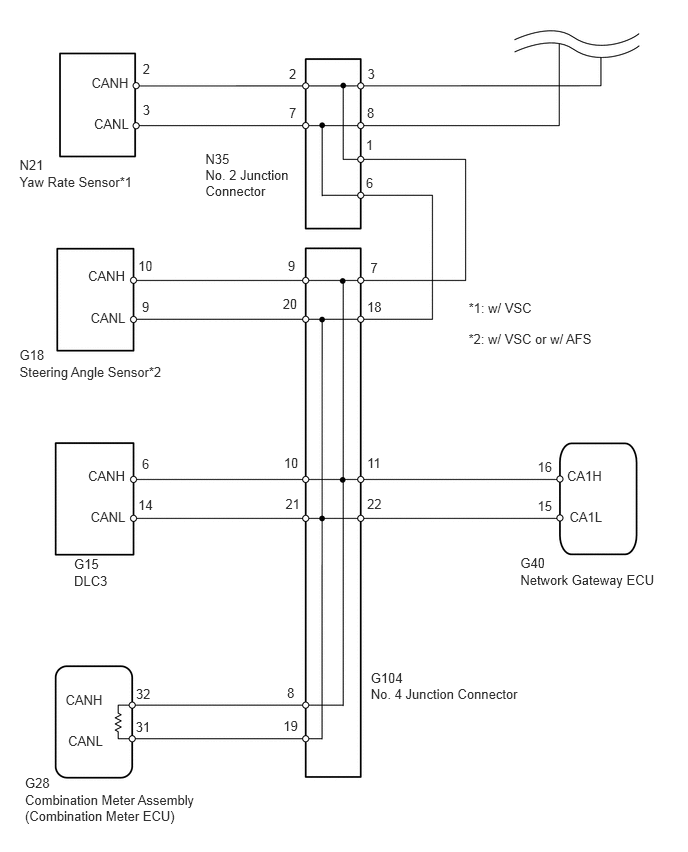
WIRING DIAGRAM
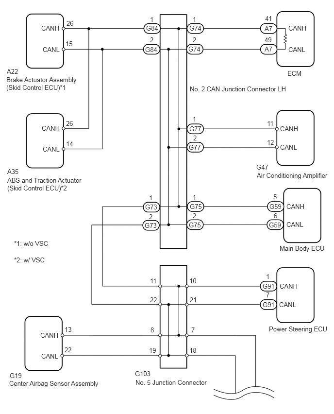
C313648E07
6.188,0.521 6.615,0.76 0.427,0.24 10 false CANH 6.188,0.979 6.594,1.219 0.406,0.24 10 false CANL 6.01,2.677 6.438,2.917 0.427,0.24 10 false CANH 6.01,3.073 6.417,3.313 0.406,0.24 10 false CANL 6.146,4.344 6.573,4.583 0.427,0.24 10 false CANH 6.146,4.729 6.552,4.969 0.406,0.24 10 false CANL 0.865,7.104 1.292,7.344 0.427,0.24 10 false CANH 0.885,7.552 1.292,7.792 0.406,0.24 10 false CANL 6,6.052 6.427,6.292 0.427,0.24 10 false CANH 5.99,6.448 6.396,6.688 0.406,0.24 10 false CANL 3.219,0.333 3.365,0.51 0.146,0.177 10 false 1 3.219,0.771 3.365,0.948 0.146,0.177 10 false 2 4.135,4.146 4.281,4.323 0.146,0.177 10 false 1 4.135,4.542 4.281,4.719 0.146,0.177 10 false 2 3.229,6.99 3.375,7.167 0.146,0.177 10 false 8 3.198,7.427 3.385,7.604 0.188,0.177 10 false 19 4.104,6.99 4.281,7.167 0.177,0.177 10 false 7 4.063,7.427 4.24,7.604 0.177,0.177 10 false 18 4.063,5.938 4.24,6.115 0.177,0.177 10 false 10 4.073,6.344 4.25,6.521 0.177,0.177 10 false 21 5.708,5.844 5.854,6.021 0.146,0.177 10 false 1 5.708,6.24 5.854,6.417 0.146,0.177 10 false 7 4.135,0.333 4.281,0.51 0.146,0.177 10 false 1 4.135,0.771 4.281,0.948 0.146,0.177 10 false 2 4.135,2.469 4.281,2.646 0.146,0.177 10 false 1 4.146,2.875 4.292,3.052 0.146,0.177 10 false 2 3.135,0.521 3.438,0.688 0.302,0.167 10 false G84 3.115,0.979 3.417,1.146 0.302,0.167 10 false G84 4.042,0.969 4.344,1.135 0.302,0.167 10 false G74 4.063,0.521 4.365,0.688 0.302,0.167 10 false G74 5.677,0.531 5.906,0.698 0.229,0.167 10 false A7 5.677,0.969 5.906,1.135 0.229,0.167 10 false A7 4.063,2.677 4.365,2.844 0.302,0.167 10 false G77 4.052,3.073 4.354,3.24 0.302,0.167 10 false G77 4.073,4.344 4.375,4.51 0.302,0.167 10 false G75 4.052,4.74 4.354,4.906 0.302,0.167 10 false G75 5.781,4.344 6.083,4.51 0.302,0.167 10 false G59 5.771,4.74 6.073,4.906 0.302,0.167 10 false G59 2.896,7.927 3.26,8.094 0.365,0.167 10 false G103 5.635,6.448 5.938,6.615 0.302,0.167 10 false G91 5.635,6.052 5.938,6.219 0.302,0.167 10 false G91 5.5,3.5 5.906,3.698 0.406,0.198 10 false G47 5.729,2.563 5.927,2.76 0.198,0.198 10 false 11 5.729,2.969 5.927,3.167 0.198,0.198 10 false 12 5.688,0.313 5.885,0.51 0.198,0.198 10 false 41 5.677,0.771 5.875,0.969 0.198,0.198 10 false 49 5.51,3.677 7.094,3.854 1.583,0.177 10 false Air Conditioning Amplifier 0.208,7.969 0.615,8.167 0.406,0.198 10 false G19 0.198,8.135 2.229,8.333 2.031,0.198 10 false Center Airbag Sensor Assembly 2.906,8.115 4.521,8.479 1.615,0.365 10 false No. 5 Junction Connector 4.073,1.823 6.229,2.073 2.156,0.25 10 false No. 2 CAN Junction Connector LH 5.771,6.969 7.094,7.219 1.323,0.25 10 false Power Steering ECU 6,5.24 7.052,5.615 1.052,0.375 10 false Main Body ECU 6.167,1.49 6.521,1.865 0.354,0.375 10 false ECM 5.865,4.135 6.063,4.333 0.198,0.198 10 false 5 5.875,4.542 6.073,4.74 0.198,0.198 10 false 6 1.385,6.979 1.583,7.177 0.198,0.198 10 false 13 1.385,7.417 1.583,7.615 0.198,0.198 10 false 22 3.198,4.156 3.344,4.333 0.146,0.177 10 false 1 3.198,4.563 3.344,4.74 0.146,0.177 10 false 2 3.115,4.354 3.417,4.521 0.302,0.167 10 false G73 3.104,4.75 3.406,4.917 0.302,0.167 10 false G73 3.219,5.938 3.396,6.115 0.177,0.177 10 false 11 3.219,6.344 3.396,6.521 0.177,0.177 10 false 22 0.885,0.521 1.313,0.76 0.427,0.24 10 false CANH 0.917,0.979 1.323,1.219 0.406,0.24 10 false CANL 0.156,3.594 0.563,3.792 0.406,0.198 10 false A35 0.156,3.781 1.833,4.156 1.677,0.375 10 false ABS and Traction Actuator (Skid Control ECU)*2 1.417,2.563 1.615,2.76 0.198,0.198 10 false 26 1.417,3 1.615,3.198 0.198,0.198 10 false 14 0.896,2.667 1.323,2.906 0.427,0.24 10 false CANH 0.917,3.115 1.323,3.354 0.406,0.24 10 false CANL 0.146,1.448 0.552,1.646 0.406,0.198 10 false A22 0.135,1.625 1.813,2 1.677,0.375 10 false Brake Actuator Assembly (Skid Control ECU)*1 1.427,0.417 1.625,0.615 0.198,0.198 10 false 26 1.406,0.854 1.604,1.052 0.198,0.198 10 false 15 0.302,5.135 1.292,5.427 0.99,0.292 10 false *1: w/o VSC 0.302,5.49 1.292,5.781 0.99,0.292 10 false *2: w/ VSC

C314267E01
2.139,1.744 3.092,2.097 0.953,0.353 10 No. 2 Junction Connector 0.203,1.817 1.607,2.170 1.403,0.353 10 Yaw Rate Sensor*1 2.139,1.574 2.473,1.765 0.334,0.192 10 N35 3.862,7.148 5.863,7.502 2.001,0.353 10 No. 4 Junction Connector 3.862,6.978 4.306,7.169 0.444,0.192 10 G104 0.203,1.64 0.640,1.832 0.437,0.192 10 N21 0.203,3.787 2.120,4.140 1.917,0.353 10 Steering Angle Sensor*2 0.203,3.61 0.640,3.801 0.437,0.192 10 G18 5.42,5.958 6.931,6.311 1.510,0.353 10 Network Gateway ECU 5.42,5.781 5.857,5.973 0.437,0.192 10 G40 0.26,8.247 2.822,8.600 2.562,0.353 10 Combination Meter Assembly (Combination Meter ECU) 0.26,8.07 0.698,8.261 0.437,0.192 10 G28 0.771,5.971 1.208,6.324 0.437,0.353 10 DLC3 0.771,5.794 1.208,5.986 0.437,0.192 10 G15 0.953,0.779 1.429,0.969 0.476,0.190 10 CANH 0.979,1.21 1.455,1.400 0.476,0.190 10 CANL 0.917,2.797 1.393,2.987 0.476,0.190 10 CANH 0.943,3.227 1.419,3.417 0.476,0.190 10 CANL 0.917,4.871 1.393,5.061 0.476,0.190 10 CANH 0.943,5.301 1.419,5.491 0.476,0.190 10 CANL 5.906,4.871 6.382,5.061 0.476,0.190 10 CA1H 5.932,5.301 6.408,5.491 0.476,0.190 10 CA1L 0.682,7.206 1.158,7.396 0.476,0.190 10 CANH 0.709,7.637 1.185,7.827 0.476,0.190 10 CANL 1.486,0.636 1.641,0.836 0.155,0.200 10 2 3.811,1.432 3.966,1.631 0.155,0.200 10 1 3.811,1.823 3.966,2.022 0.155,0.200 10 6 3.823,3.112 4.028,3.312 0.205,0.200 10 18 1.439,2.688 1.644,2.887 0.205,0.200 10 10 1.439,5.182 1.644,5.382 0.205,0.200 10 14 2.951,7.477 3.156,7.677 0.205,0.200 10 19 2.957,4.736 3.162,4.936 0.205,0.200 10 10 3.824,4.736 4.030,4.936 0.205,0.200 10 11 5.599,4.779 5.804,4.978 0.205,0.200 10 16 5.599,5.188 5.804,5.387 0.205,0.200 10 15 3.824,5.166 4.030,5.365 0.205,0.200 10 22 1.416,7.148 1.621,7.347 0.205,0.200 10 32 2.945,3.084 3.151,3.283 0.205,0.200 10 20 2.973,5.168 3.178,5.368 0.205,0.200 10 21 1.413,7.492 1.618,7.691 0.205,0.200 10 31 3.01,0.687 3.165,0.886 0.155,0.200 10 2 3.828,0.685 3.983,0.885 0.155,0.200 10 3 3.822,1.098 3.978,1.297 0.155,0.200 10 8 3.01,1.089 3.165,1.288 0.155,0.200 10 7 3.858,2.707 4.013,2.906 0.155,0.200 10 7 1.486,1.066 1.641,1.266 0.155,0.200 10 3 1.478,3.115 1.633,3.314 0.155,0.200 10 9 1.478,4.75 1.633,4.949 0.155,0.200 10 6 2.99,7.135 3.145,7.334 0.155,0.200 10 8 2.998,2.685 3.154,2.884 0.155,0.200 10 9 4.881,3.126 6.797,3.479 1.917,0.353 10 *1: w/ VSC 4.88,3.444 6.796,3.797 1.917,0.353 10 *2: w/ VSC or w/ AFS

CAUTION / NOTICE / HINT

NOTICE:

Turn the engine switch off before measuring the resistances of the main wire and the branch wire.


HINT:

Operating the engine switch, any switches or any doors triggers related ECU and sensor communication with the CAN, which causes resistance variation.


PROCEDURE

1.CHECK CAN BUS LINE FOR SHORT TO GND (DLC3 BRANCH WIRE)
a.

Disconnect the G104 No. 4 junction connector.

b.
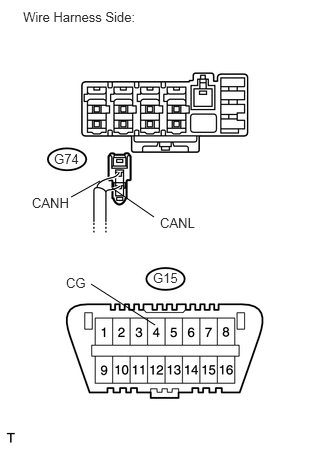
U190034E01
1.533,0.273 1.813,0.460 0.280,0.187 10 G15 1.753,1.769 2.179,1.933 0.426,0.163 10 CANL 2.534,0.294 2.960,0.458 0.426,0.163 10 CANH 0.782,0.294 1.036,0.470 0.254,0.176 10 CG 1.609,0.879 1.092,0.409 false 1.977,0.895 2.463,0.416 false 1.972,1.427 1.934,1.726 false

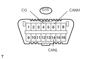
Measure the resistance of the DLC3.

Standard resistance:
Tester Connection Condition Specified Condition
G15-6 (CANH) - G15-4 (CG) Engine switch off 1 MΩ or higher
G15-14 (CANL) - G15-4 (CG) Engine switch off 1 MΩ or higher


OK

2.CHECK CAN BUS LINE FOR SHORT TO GND (NO. 2 CAN JUNCTION CONNECTOR LH SIDE)

NG

REPAIR OR REPLACE CAN BRANCH WIRE CONNECTED TO DLC3 (CANH, CANL)

2.CHECK CAN BUS LINE FOR SHORT TO GND (NO. 2 CAN JUNCTION CONNECTOR LH SIDE)
a.

Reconnect the G104 No. 4 junction connector.


b.

Disconnect the G73 No. 2 CAN junction connector LH connector.


c.
U190034E01
1.533,0.273 1.813,0.460 0.280,0.187 10 G15 1.753,1.769 2.179,1.933 0.426,0.163 10 CANL 2.534,0.294 2.960,0.458 0.426,0.163 10 CANH 0.782,0.294 1.036,0.470 0.254,0.176 10 CG 1.609,0.879 1.092,0.409 false 1.977,0.895 2.463,0.416 false 1.972,1.427 1.934,1.726 false

Measure the resistance of the DLC3.

Standard resistance:
Tester Connection Condition Specified Condition
G15-6 (CANH) - G15-4 (CG) Engine switch off 200 Ω or higher
G15-14 (CANL) - G15-4 (CG) Engine switch off 200 Ω or higher


OK

3.CHECK CAN BUS LINE FOR SHORT TO GND (NO. 2 CAN JUNCTION CONNECTOR LH - SKID CONTROL ECU)

NG

11.CHECK CAN BUS LINE FOR SHORT TO GND (NO. 5 JUNCTION CONNECTOR SIDE)
3.CHECK CAN BUS LINE FOR SHORT TO GND (NO. 2 CAN JUNCTION CONNECTOR LH - SKID CONTROL ECU)
a.

Reconnect the G73 No. 2 CAN junction connector LH connector.


b.

Disconnect the G84 No. 2 CAN junction connector LH connector.


c.
U190034E01
1.533,0.273 1.813,0.460 0.280,0.187 10 G15 1.753,1.769 2.179,1.933 0.426,0.163 10 CANL 2.534,0.294 2.960,0.458 0.426,0.163 10 CANH 0.782,0.294 1.036,0.470 0.254,0.176 10 CG 1.609,0.879 1.092,0.409 false 1.977,0.895 2.463,0.416 false 1.972,1.427 1.934,1.726 false

Measure the resistance of the DLC3.

Standard resistance:
Tester Connection Condition Specified Condition
G15-6 (CANH) - G15-4 (CG) Engine switch off 200 Ω or higher
G15-14 (CANL) - G15-4 (CG) Engine switch off 200 Ω or higher


OK

4.CHECK CAN BUS LINE FOR SHORT TO GND (SKID CONTROL ECU BRANCH WIRE)

NG

5.CHECK CAN BUS LINE FOR SHORT TO GND (NO. 2 CAN JUNCTION CONNECTOR LH - ECM)
4.CHECK CAN BUS LINE FOR SHORT TO GND (SKID CONTROL ECU BRANCH WIRE)
a.

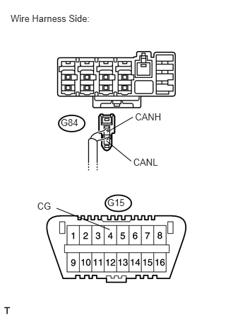
Disconnect the A35 ABS and traction actuator (skid control ECU) connector or A22 brake actuator assembly (skid control ECU) connector.

b.
U189679E01
1.965,2.299 2.377,2.462 0.413,0.163 10 CANL 1.568,2.069 1.935,2.37 false 1.577,1.943 1.96,1.722 false 1.992,1.633 2.405,1.796 0.413,0.163 10 CANH 0.894,1.721 1.176,1.868 0.283,0.147 10 G84 0.156,0.185 1.441,0.359 1.286,0.174 10 Wire Harness Side: 1.581,2.898 1.864,3.045 0.283,0.147 10 G15 0.548,2.951 0.917,3.098 0.369,0.147 10 CG 1.619,3.378 0.834,3.062 false

Measure the resistance of the wire harness side connector.

Standard resistance:
Tester Connection Condition Specified Condition
G84-1 (CANH) - G15-4 (CG) Engine switch off 200 Ω or higher
G84-2 (CANL) - G15-4 (CG) Engine switch off 200 Ω or higher


Result:
OK (w/ VSC) A
OK (w/o VSC) B
NG C


A

REPLACE ABS AND TRACTION ACTUATOR (SKID CONTROL ECU)

B

REPLACE BRAKE ACTUATOR ASSEMBLY (SKID CONTROL ECU)

C

REPAIR OR REPLACE CAN BRANCH WIRE CONNECTED TO SKID CONTROL ECU (CANH, CANL)

5.CHECK CAN BUS LINE FOR SHORT TO GND (NO. 2 CAN JUNCTION CONNECTOR LH - ECM)
a.

Disconnect the G74 No. 2 CAN junction connector LH connector.


b.
U190034E01
1.533,0.273 1.813,0.460 0.280,0.187 10 G15 1.753,1.769 2.179,1.933 0.426,0.163 10 CANL 2.534,0.294 2.960,0.458 0.426,0.163 10 CANH 0.782,0.294 1.036,0.470 0.254,0.176 10 CG 1.609,0.879 1.092,0.409 false 1.977,0.895 2.463,0.416 false 1.972,1.427 1.934,1.726 false

Measure the resistance of the DLC3.

Standard resistance:
Tester Connection Condition Specified Condition
G15-6 (CANH) - G15-4 (CG) Engine switch off 200 Ω or higher
G15-14 (CANL) - G15-4 (CG) Engine switch off 200 Ω or higher


OK

6.CHECK CAN BUS LINE FOR SHORT TO GND (ECM MAIN WIRE)

NG

7.CHECK CAN BUS LINE FOR SHORT TO GND (NO. 2 CAN JUNCTION CONNECTOR LH - AIR CONDITIONING AMPLIFIER)
6.CHECK CAN BUS LINE FOR SHORT TO GND (ECM MAIN WIRE)
a.

Disconnect the A7 ECM connector.


b.
U189371E02
1.042,1.885 0.74,2.052 false 1.167,1.958 1.604,2.26 false 1.615,3.385 0.948,2.958 false 0.563,1.573 0.854,1.729 0.292,0.156 10 false G74 0.333,2.031 0.75,2.177 0.417,0.146 10 false CANH 1.667,2.24 2.083,2.385 0.417,0.146 10 false CANL 0.688,2.865 0.927,3.01 0.24,0.146 10 false CG 1.594,2.813 1.885,2.969 0.292,0.156 10 false G15 0.24,0.094 1.563,0.271 1.323,0.177 10 false Wire Harness Side:

Measure the resistance of the wire harness side connector.

Standard resistance:
Tester Connection Condition Specified Condition
G74-1 (CANH) - G15-4 (CG) Engine switch off 200 Ω or higher
G74-2 (CANL) - G15-4 (CG) Engine switch off 200 Ω or higher


OK

REPLACE ECM

NG

REPAIR OR REPLACE CAN MAIN WIRE CONNECTED TO ECM (CANH, CANL)

7.CHECK CAN BUS LINE FOR SHORT TO GND (NO. 2 CAN JUNCTION CONNECTOR LH - AIR CONDITIONING AMPLIFIER)
a.

Disconnect the G77 No. 2 CAN junction connector LH connector.


b.
U190034E01
1.533,0.273 1.813,0.460 0.280,0.187 10 G15 1.753,1.769 2.179,1.933 0.426,0.163 10 CANL 2.534,0.294 2.960,0.458 0.426,0.163 10 CANH 0.782,0.294 1.036,0.470 0.254,0.176 10 CG 1.609,0.879 1.092,0.409 false 1.977,0.895 2.463,0.416 false 1.972,1.427 1.934,1.726 false

Measure the resistance of the DLC3.

Standard resistance:
Tester Connection Condition Specified Condition
G15-6 (CANH) - G15-4 (CG) Engine switch off 200 Ω or higher
G15-14 (CANL) - G15-4 (CG) Engine switch off 200 Ω or higher


OK

8.CHECK CAN BUS LINE FOR SHORT TO GND (AIR CONDITIONING AMPLIFIER BRANCH WIRE)

NG

9.CHECK CAN BUS LINE FOR SHORT TO GND (NO. 2 CAN JUNCTION CONNECTOR LH - MAIN BODY ECU)
8.CHECK CAN BUS LINE FOR SHORT TO GND (AIR CONDITIONING AMPLIFIER BRANCH WIRE)
a.

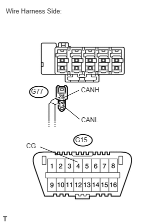
Disconnect the G47 air conditioning amplifier connector.

b.
U189682E01
1.689,2.418 2.102,2.581 0.413,0.163 10 CANL 1.293,2.188 1.659,2.49 false 1.285,2.058 1.644,1.885 false 1.686,1.788 2.120,1.951 0.434,0.163 10 CANH 1.564,2.838 1.847,2.985 0.283,0.147 10 G15 0.121,0.15 1.407,0.325 1.286,0.174 10 Wire Harness Side: 0.544,2.958 0.913,3.105 0.369,0.147 10 CG 1.623,3.386 0.833,3.066 false 0.645,1.825 0.927,1.973 0.283,0.147 10 G77

Measure the resistance of the wire harness side connector.

Standard resistance:
Tester Connection Condition Specified Condition
G77-1 (CANH) - G15-4 (CG) Engine switch off 200 Ω or higher
G77-2 (CANL) - G15-4 (CG) Engine switch off 200 Ω or higher


OK

REPLACE AIR CONDITIONING AMPLIFIER

NG

REPAIR OR REPLACE CAN BRANCH WIRE CONNECTED TO AIR CONDITIONING AMPLIFIER (CANH, CANL)

9.CHECK CAN BUS LINE FOR SHORT TO GND (NO. 2 CAN JUNCTION CONNECTOR LH - MAIN BODY ECU)
a.

Disconnect the G75 No. 2 CAN junction connector LH connector.


b.
U190034E01
1.533,0.273 1.813,0.460 0.280,0.187 10 G15 1.753,1.769 2.179,1.933 0.426,0.163 10 CANL 2.534,0.294 2.960,0.458 0.426,0.163 10 CANH 0.782,0.294 1.036,0.470 0.254,0.176 10 CG 1.609,0.879 1.092,0.409 false 1.977,0.895 2.463,0.416 false 1.972,1.427 1.934,1.726 false

Measure the resistance of the DLC3.

Standard resistance:
Tester Connection Condition Specified Condition
G15-6 (CANH) - G15-4 (CG) Engine switch off 200 Ω or higher
G15-14 (CANL) - G15-4 (CG) Engine switch off 200 Ω or higher


OK

10.CHECK CAN BUS LINE FOR SHORT TO GND (MAIN BODY ECU BRANCH WIRE)

NG

REPAIR OR REPLACE NO. 2 CAN JUNCTION CONNECTOR LH

10.CHECK CAN BUS LINE FOR SHORT TO GND (MAIN BODY ECU BRANCH WIRE)
a.

Disconnect the G59 main body ECU connector.
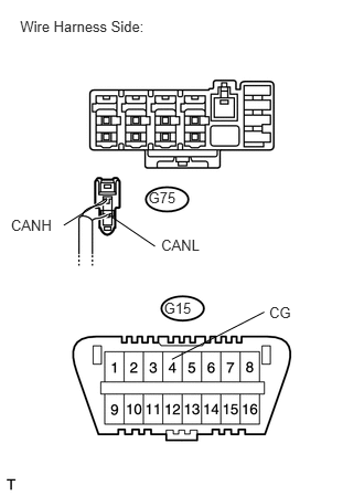

b.
U189735E01
1.401,1.785 1.696,1.941 0.295,0.156 10 G75 0.103,2.047 0.523,2.196 0.420,0.149 10 CANH 1.009,1.869 0.602,2.124 false 1.522,2.231 1.942,2.380 0.420,0.149 10 CANL 1.026,2.025 1.463,2.322 false 2.542,2.867 2.832,3.009 0.290,0.142 10 CG 1.623,3.388 2.496,2.942 false 1.548,2.818 1.843,2.973 0.295,0.156 10 G15 0.19,0.167 1.513,0.342 1.323,0.174 10 Wire Harness Side:

Measure the resistance of the wire harness side connector.

Standard resistance:
Tester Connection Condition Specified Condition
G75-1 (CANH) - G15-4 (CG) Engine switch off 200 Ω or higher
G75-2 (CANL) - G15-4 (CG) Engine switch off 200 Ω or higher


OK

REPLACE MAIN BODY ECU

NG

REPAIR OR REPLACE CAN BRANCH WIRE CONNECTED TO MAIN BODY ECU (CANH, CANL)

11.CHECK CAN BUS LINE FOR SHORT TO GND (NO. 5 JUNCTION CONNECTOR SIDE)
a.

Disconnect the G103 No. 5 junction connector.


b.
U190034E01
1.533,0.273 1.813,0.460 0.280,0.187 10 G15 1.753,1.769 2.179,1.933 0.426,0.163 10 CANL 2.534,0.294 2.960,0.458 0.426,0.163 10 CANH 0.782,0.294 1.036,0.470 0.254,0.176 10 CG 1.609,0.879 1.092,0.409 false 1.977,0.895 2.463,0.416 false 1.972,1.427 1.934,1.726 false

Measure the resistance of the DLC3.

Standard resistance:
Tester Connection Condition Specified Condition
G15-6 (CANH) - G15-4 (CG) Engine switch off 200 Ω or higher
G15-14 (CANL) - G15-4 (CG) Engine switch off 200 Ω or higher


OK

12.CHECK CAN BUS LINE FOR SHORT TO GND (NO. 2 CAN JUNCTION CONNECTOR LH - NO. 5 JUNCTION CONNECTOR)

NG

17.CHECK CAN BUS LINE FOR SHORT TO GND (NO. 5 JUNCTION CONNECTOR - NO. 2 JUNCTION CONNECTOR)
12.CHECK CAN BUS LINE FOR SHORT TO GND (NO. 2 CAN JUNCTION CONNECTOR LH - NO. 5 JUNCTION CONNECTOR)
a.
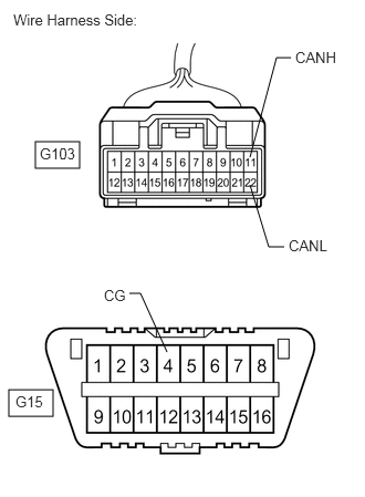
C366276E14
0.333,1.333 0.75,1.583 0.417,0.25 0.083,3.667 0.5,3.917 0.417,0.25 2.354,1.479 2.604,0.542 2.604,0.542 2.74,0.542 false 2.677,2.323 2.531,2.323 2.531,2.323 2.354,1.74 false 1.219,2.76 1.323,2.76 1.323,2.76 1.573,3.313 false 0.125,0.104 1.531,0.427 1.406,0.323 10 false Wire Harness Side: 0.375,1.365 0.875,1.646 0.5,0.281 10 false G103 0.146,3.698 0.646,3.979 0.5,0.281 10 false G15 2.781,0.458 3.281,0.74 0.5,0.281 10 false CANH 2.719,2.229 3.219,2.51 0.5,0.281 10 false CANL 0.979,2.698 1.479,2.979 0.5,0.281 10 false CG

Measure the resistance of the wire harness side connector.

Standard resistance:
Tester Connection Condition Specified Condition
G103-11 (CANH) - G15-4 (CG) Engine switch off 200 Ω or higher
G103-22 (CANL) - G15-4 (CG) Engine switch off 200 Ω or higher


OK

13.CHECK CAN BUS LINE FOR SHORT TO GND (NO. 5 JUNCTION CONNECTOR - POWER STEERING ECU)

NG

REPAIR OR REPLACE CAN MAIN WIRE OR CONNECTOR (NO. 2 CAN JUNCTION CONNECTOR LH - NO. 5 JUNCTION CONNECTOR)

13.CHECK CAN BUS LINE FOR SHORT TO GND (NO. 5 JUNCTION CONNECTOR - POWER STEERING ECU)
a.

Reconnect the G73 No. 2 CAN junction connector LH connector.


b.

Reconnect the G103 No. 5 junction connector.


c.

Disconnect the G91 power steering ECU connector.
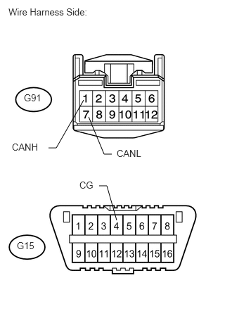

d.
U189662E02
0.719,2.188 0.833,2.188 0.833,2.188 1.24,1.479 false 1.313,1.729 1.542,2.281 1.542,2.281 1.656,2.281 false 1.469,2.75 1.583,2.75 1.583,2.75 1.729,3.26 false 0.125,0.094 2.073,0.333 1.948,0.24 10 false Wire Harness Side: 0.354,1.365 0.667,1.552 0.313,0.188 10 false G91 0.25,3.552 0.563,3.74 0.313,0.188 10 false G15 0.177,2.094 0.688,2.292 0.51,0.198 10 false CANH 1.729,2.188 2.24,2.385 0.51,0.198 10 false CANL 1.177,2.656 1.49,2.854 0.313,0.198 10 false CG

Measure the resistance of the wire harness side connector.

Standard resistance:
Tester Connection Condition Specified Condition
G91-1 (CANH) - G15-4 (CG) Engine switch off 200 Ω or higher
G91-7 (CANL) - G15-4 (CG) Engine switch off 200 Ω or higher


OK

REPLACE POWER STEERING ECU

NG

14.CHECK CAN BUS LINE FOR SHORT TO GND (POWER STEERING ECU BRANCH WIRE)
a.

Disconnect the G103 No. 5 junction connector.
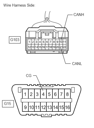

b.
C366276E15
0.333,1.333 0.75,1.583 0.417,0.25 0.083,3.667 0.5,3.917 0.417,0.25 2.229,1.479 2.479,0.542 2.479,0.542 2.656,0.542 false 2.583,2.323 2.396,2.323 2.396,2.323 2.219,1.74 false 1.208,2.76 1.323,2.76 1.323,2.76 1.573,3.313 false 0.125,0.104 1.531,0.427 1.406,0.323 10 false Wire Harness Side: 0.375,1.365 0.875,1.646 0.5,0.281 10 false G103 0.146,3.698 0.646,3.979 0.5,0.281 10 false G15 2.688,0.448 3.188,0.729 0.5,0.281 10 false CANH 2.635,2.24 3.135,2.521 0.5,0.281 10 false CANL 0.948,2.677 1.448,2.958 0.5,0.281 10 false CG

Measure the resistance of the wire harness side connector.

Standard resistance:
Tester Connection Condition Specified Condition
G103-10 (CANH) - G15-4 (CG) Engine switch off 200 Ω or higher
G103-21 (CANL) - G15-4 (CG) Engine switch off 200 Ω or higher


OK

15.CHECK CAN BUS LINE FOR SHORT TO GND (NO. 5 JUNCTION CONNECTOR - CENTER AIRBAG SENSOR ASSEMBLY)

NG

REPAIR OR REPLACE CAN BRANCH WIRE CONNECTED TO POWER STEERING ECU (CANH, CANL)

15.CHECK CAN BUS LINE FOR SHORT TO GND (NO. 5 JUNCTION CONNECTOR - CENTER AIRBAG SENSOR ASSEMBLY)
a.

Reconnect the G103 No. 5 junction connector.


b.

Disconnect the G19 center airbag sensor assembly connector.
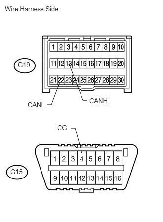

c.
U189666E02
1,2.208 1.083,2.208 1.083,2.208 1.271,1.698 false 1.5,2.698 1.583,2.698 1.583,2.698 1.729,3.229 false 1.833,2.115 1.75,2.115 1.75,2.115 1.448,1.323 false 0.104,0.104 1.896,0.417 1.792,0.313 10 false Wire Harness Side: 1.885,2.042 2.375,2.198 0.49,0.156 10 false CANH 0.583,2.125 1.073,2.281 0.49,0.156 10 false CANL 1.208,2.604 1.552,2.76 0.344,0.156 10 false CG 0.375,1.281 0.708,1.615 0.333,0.333 10 false G19 0.219,3.531 0.552,3.865 0.333,0.333 10 false G15

Measure the resistance of the wire harness side connector.

Standard resistance:
Tester Connection Condition Specified Condition
G19-13 (CANH) - G15-4 (CG) Engine switch off 200 Ω or higher
G19-22 (CANL) - G15-4 (CG) Engine switch off 200 Ω or higher


OK

REPLACE CENTER AIRBAG SENSOR ASSEMBLY

NG

16.CHECK CAN BUS LINE FOR SHORT TO GND (CENTER AIRBAG SENSOR ASSEMBLY BRANCH WIRE)
a.

Disconnect the G103 No. 5 junction connector.
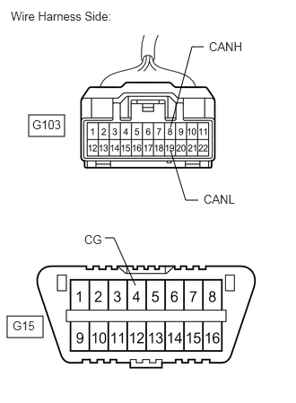

b.
C366276E16
0.333,1.333 0.75,1.583 0.417,0.25 0.083,3.667 0.5,3.917 0.417,0.25 1.979,1.479 2.229,0.542 2.229,0.542 2.365,0.542 false 2.302,2.323 2.156,2.323 2.156,2.323 1.979,1.74 false 1.219,2.76 1.323,2.76 1.323,2.76 1.573,3.313 false 0.125,0.104 1.531,0.427 1.406,0.323 10 false Wire Harness Side: 0.375,1.365 0.875,1.646 0.5,0.281 10 false G103 0.146,3.698 0.646,3.979 0.5,0.281 10 false G15 2.427,0.458 2.927,0.74 0.5,0.281 10 false CANH 2.365,2.229 2.865,2.51 0.5,0.281 10 false CANL 0.979,2.698 1.479,2.979 0.5,0.281 10 false CG

Measure the resistance of the wire harness side connector.

Standard resistance:
Tester Connection Condition Specified Condition
G103-8 (CANH) - G15-4 (CG) Engine switch off 200 Ω or higher
G103-19 (CANL) - G15-4 (CG) Engine switch off 200 Ω or higher


OK

REPAIR OR REPLACE NO. 5 JUNCTION CONNECTOR

NG

REPAIR OR REPLACE CAN BRANCH WIRE CONNECTED TO CENTER AIRBAG SENSOR ASSEMBLY (CANH, CANL)

17.CHECK CAN BUS LINE FOR SHORT TO GND (NO. 5 JUNCTION CONNECTOR - NO. 2 JUNCTION CONNECTOR)
a.

Disconnect the N35 No. 2 junction connector.
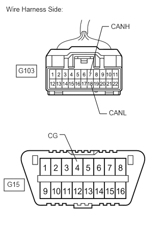

b.
C366276E17
0.333,1.333 0.75,1.583 0.417,0.25 0.083,3.667 0.5,3.917 0.417,0.25 1.844,1.479 2.094,0.542 2.094,0.542 2.229,0.542 false 2.188,2.333 2.042,2.333 2.042,2.333 1.865,1.75 false 1.219,2.76 1.323,2.76 1.323,2.76 1.573,3.313 false 0.125,0.104 1.531,0.427 1.406,0.323 10 false Wire Harness Side: 0.375,1.365 0.875,1.646 0.5,0.281 10 false G103 0.146,3.698 0.646,3.979 0.5,0.281 10 false G15 2.271,0.458 2.771,0.74 0.5,0.281 10 false CANH 2.229,2.229 2.729,2.51 0.5,0.281 10 false CANL 0.979,2.698 1.479,2.979 0.5,0.281 10 false CG

Measure the resistance of the wire harness side connector.

Standard resistance:
Tester Connection Condition Specified Condition
G103-7 (CANH) - G15-4 (CG) Engine switch off 200 Ω or higher
G103-18 (CANL) - G15-4 (CG) Engine switch off 200 Ω or higher


OK

18.CHECK CAN BUS LINE FOR SHORT TO GND (NO. 2 JUNCTION CONNECTOR SIDE)

NG

REPAIR OR REPLACE CAN MAIN WIRE OR CONNECTOR (NO. 5 JUNCTION CONNECTOR - NO. 2 JUNCTION CONNECTOR)

18.CHECK CAN BUS LINE FOR SHORT TO GND (NO. 2 JUNCTION CONNECTOR SIDE)
a.

Reconnect the G73 No. 2 CAN junction connector LH connector.


b.

Reconnect the G103 No. 5 junction connector.


c.
U190034E01
1.533,0.273 1.813,0.460 0.280,0.187 10 G15 1.753,1.769 2.179,1.933 0.426,0.163 10 CANL 2.534,0.294 2.960,0.458 0.426,0.163 10 CANH 0.782,0.294 1.036,0.470 0.254,0.176 10 CG 1.609,0.879 1.092,0.409 false 1.977,0.895 2.463,0.416 false 1.972,1.427 1.934,1.726 false

Measure the resistance of the DLC3.

Standard resistance:
Tester Connection Condition Specified Condition
G15-6 (CANH) - G15-4 (CG) Engine switch off 200 Ω or higher
G15-14 (CANL) - G15-4 (CG) Engine switch off 200 Ω or higher


OK

19.CHECK CAN BUS LINE FOR SHORT TO GND (NO. 2 JUNCTION CONNECTOR - YAW RATE SENSOR)

NG

21.CHECK CAN BUS LINE FOR SHORT TO GND (NO. 2 JUNCTION CONNECTOR - NO. 4 JUNCTION CONNECTOR)
19.CHECK CAN BUS LINE FOR SHORT TO GND (NO. 2 JUNCTION CONNECTOR - YAW RATE SENSOR)
a.

Reconnect the N35 No. 2 junction connector.


b.

Disconnect the N21 yaw rate sensor connector.
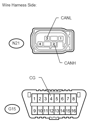

c.
U189658E02
2.104,2.125 2.021,2.125 2.021,2.125 1.833,1.51 false 1.979,0.604 1.896,0.604 1.896,0.604 1.583,1.271 false 1.302,2.625 1.396,2.625 1.396,2.625 1.708,3.25 false 0.073,0.083 1.427,0.427 1.354,0.344 10 false Wire Harness Side: 2.167,2.052 2.667,2.24 0.5,0.188 10 false CANH 0.99,2.552 1.49,2.74 0.5,0.188 10 false CG 2.052,0.521 2.552,0.708 0.5,0.188 10 false CANL 0.417,1.375 0.75,1.563 0.333,0.188 10 false N21 0.281,3.604 0.615,3.792 0.333,0.188 10 false G15

Measure the resistance of the wire harness side connector.

Standard resistance:
Tester Connection Condition Specified Condition
N21-2 (CANH) - G15-4 (CG) Engine switch off 200 Ω or higher
N21-3 (CANL) - G15-4 (CG) Engine switch off 200 Ω or higher


OK

REPLACE YAW RATE SENSOR

NG

20.CHECK CAN BUS LINE FOR SHORT TO GND (YAW RATE SENSOR BRANCH WIRE)
a.

Disconnect the N35 No. 2 junction connector.
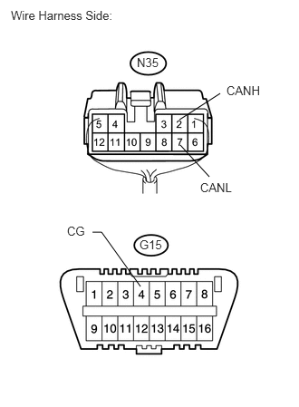

b.
U189265E02
2.073,1.667 2.406,2.031 false 2.063,1.375 2.531,1.073 false 1.615,3.292 1.167,2.667 1.167,2.667 1.063,2.667 false 0.125,0.094 1.521,0.26 1.396,0.167 10 false Wire Harness Side: 1.604,2.729 1.885,2.896 0.281,0.167 10 false G15 1.573,0.635 1.896,0.802 0.323,0.167 10 false N35 2.604,0.958 3.052,1.125 0.448,0.167 10 false CANH 2.302,2.073 2.75,2.24 0.448,0.167 10 false CANL 0.771,2.573 1.083,2.75 0.313,0.177 10 false CG

Measure the resistance of the wire harness side connectors.

Standard resistance:
Tester Connection Condition Specified Condition
N35-2 (CANH) - G15-4 (CG) Engine switch off 200 Ω or higher
N35-7 (CANL) - G15-4 (CG) Engine switch off 200 Ω or higher


OK

REPAIR OR REPLACE NO. 2 JUNCTION CONNECTOR

NG

REPAIR OR REPLACE CAN BRANCH WIRE CONNECTED TO YAW RATE SENSOR (CANH, CANL)

21.CHECK CAN BUS LINE FOR SHORT TO GND (NO. 2 JUNCTION CONNECTOR - NO. 4 JUNCTION CONNECTOR)
a.

Disconnect the G104 No. 4 junction connector.
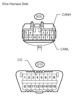

b.
U189266E02
2.24,1.646 2.479,2.156 2.479,2.156 2.583,2.156 false 2.25,1.365 2.469,0.635 2.469,0.635 2.625,0.635 false 1.594,3.292 1.188,2.635 1.188,2.635 1.073,2.635 false 0.094,0.083 1.49,0.25 1.396,0.167 10 false Wire Harness Side: 1.604,2.729 1.885,2.896 0.281,0.167 10 false G15 1.583,0.635 1.906,0.802 0.323,0.167 10 false N35 2.698,0.552 3.146,0.719 0.448,0.167 10 false CANH 2.635,2.063 3.083,2.229 0.448,0.167 10 false CANL 0.76,2.531 1.073,2.708 0.313,0.177 10 false CG

Measure the resistance of the wire harness side connector.

Standard resistance:
Tester Connection Condition Specified Condition
N35-1 (CANH) - G15-4 (CG) Engine switch off 200 Ω or higher
N35-6 (CANL) - G15-4 (CG) Engine switch off 200 Ω or higher


OK

22.CHECK CAN BUS LINE FOR SHORT TO GND (NO. 4 JUNCTION CONNECTOR - STEERING ANGLE SENSOR)

NG

REPAIR OR REPLACE CAN MAIN WIRE OR CONNECTOR (NO. 2 JUNCTION CONNECTOR - NO. 4 JUNCTION CONNECTOR)

22.CHECK CAN BUS LINE FOR SHORT TO GND (NO. 4 JUNCTION CONNECTOR - STEERING ANGLE SENSOR)
a.

Reconnect the N35 No. 2 junction connector.


b.

Reconnect the G104 No. 4 junction connector.


c.

Disconnect the G18 steering angle sensor connector.
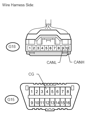

d.
U189660E02
2.115,2.281 2.188,2.281 2.188,2.281 2.292,1.781 false 1.333,2.708 1.406,2.708 1.406,2.708 1.698,3.25 false 2.646,2.271 2.563,2.271 2.563,2.271 2.458,1.781 false 0.083,0.094 1.5,0.396 1.417,0.302 10 false Wire Harness Side: 2.698,2.188 3.188,2.375 0.49,0.188 10 false CANH 1.708,2.198 2.198,2.385 0.49,0.188 10 false CANL 1.042,2.625 1.531,2.813 0.49,0.188 10 false CG 0.313,1.615 0.646,1.781 0.333,0.167 10 false G18 0.271,3.552 0.604,3.719 0.333,0.167 10 false G15

Measure the resistance of the wire harness side connector.

Standard resistance:
Tester Connection Condition Specified Condition
G18-10 (CANH) - G15-4 (CG) Engine switch off 200 Ω or higher
G18-9 (CANL) - G15-4 (CG) Engine switch off 200 Ω or higher


OK

REPLACE STEERING ANGLE SENSOR

NG

23.CHECK CAN BUS LINE FOR SHORT TO GND (STEERING ANGLE SENSOR BRANCH WIRE)
a.

Disconnect the G104 No. 4 junction connector.
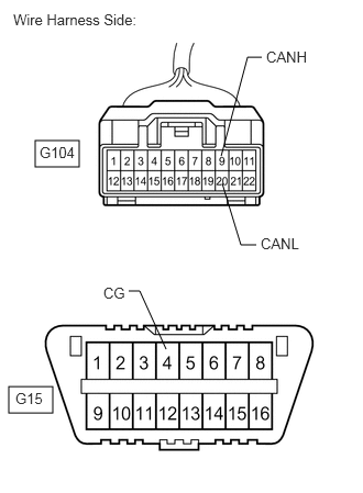

b.
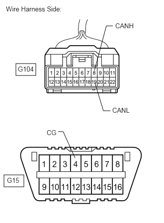
C366276E18
0.333,1.333 0.75,1.583 0.417,0.25 0.083,3.667 0.5,3.917 0.417,0.25 2.094,1.479 2.344,0.542 2.344,0.542 2.479,0.542 false 2.427,2.323 2.281,2.323 2.281,2.323 2.104,1.74 false 1.219,2.76 1.323,2.76 1.323,2.76 1.573,3.313 false 0.125,0.104 1.531,0.427 1.406,0.323 10 false Wire Harness Side: 0.375,1.365 0.875,1.646 0.5,0.281 10 false G104 0.146,3.698 0.646,3.979 0.5,0.281 10 false G15 2.521,0.458 3.021,0.74 0.5,0.281 10 false CANH 2.469,2.229 2.969,2.51 0.5,0.281 10 false CANL 0.979,2.698 1.479,2.979 0.5,0.281 10 false CG

Measure the resistance of the wire harness side connector.


Standard resistance:
Tester Connection Condition Specified Condition
G104-9 (CANH) - G15-4 (CG) Engine switch off 200 Ω or higher
G104-20 (CANL) - G15-4 (CG) Engine switch off 200 Ω or higher


OK

24.CHECK CAN BUS LINE FOR SHORT TO GND (NO. 4 JUNCTION CONNECTOR - NETWORK GATEWAY ECU)

NG

REPAIR OR REPLACE CAN BRANCH WIRE CONNECTED TO STEERING ANGLE SENSOR (CANH, CANL)

24.CHECK CAN BUS LINE FOR SHORT TO GND (NO. 4 JUNCTION CONNECTOR - NETWORK GATEWAY ECU)
a.

Reconnect the G104 No. 4 junction connector.


b.

Disconnect the G40 network gateway ECU connector.
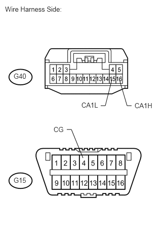

c.
U189664E02
2.073,2.167 2.167,2.167 2.167,2.167 2.302,1.635 false 1.375,2.656 1.469,2.656 1.469,2.656 1.708,3.24 false 2.708,2.167 2.615,2.167 2.615,2.167 2.458,1.635 false 0.104,0.104 1.521,0.344 1.417,0.24 10 false Wire Harness Side: 2.771,2.083 3.271,2.281 0.5,0.198 10 false CA1H 1.677,2.073 2.146,2.24 0.469,0.167 10 false CA1L 1.104,2.573 1.573,2.74 0.469,0.167 10 false CG 0.281,1.479 0.615,1.688 0.333,0.208 10 false G40 0.281,3.615 0.615,3.823 0.333,0.208 10 false G15

Measure the resistance of the wire harness side connector.

Standard resistance:
Tester Connection Condition Specified Condition
G40-16 (CA1H) - G15-4 (CG) Engine switch off 200 Ω or higher
G40-15 (CA1L) - G15-4 (CG) Engine switch off 200 Ω or higher


OK

REPLACE NETWORK GATEWAY ECU

NG

25.CHECK CAN BUS LINE FOR SHORT TO GND (NETWORK GATEWAY ECU BRANCH WIRE)
a.

Disconnect the G104 No. 4 junction connector.
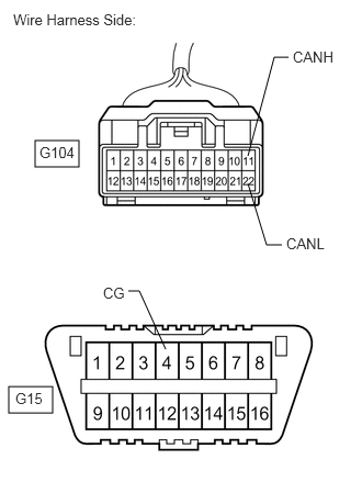

b.
C366276E19
0.333,1.333 0.75,1.583 0.417,0.25 0.083,3.667 0.5,3.917 0.417,0.25 2.354,1.479 2.604,0.542 2.604,0.542 2.74,0.542 false 2.677,2.323 2.531,2.323 2.531,2.323 2.354,1.74 false 1.219,2.76 1.323,2.76 1.323,2.76 1.573,3.313 false 0.125,0.104 1.531,0.427 1.406,0.323 10 false Wire Harness Side: 0.375,1.365 0.875,1.646 0.5,0.281 10 false G104 0.146,3.698 0.646,3.979 0.5,0.281 10 false G15 2.781,0.458 3.281,0.74 0.5,0.281 10 false CANH 2.719,2.229 3.219,2.51 0.5,0.281 10 false CANL 0.979,2.698 1.479,2.979 0.5,0.281 10 false CG

Measure the resistance of the wire harness side connector.

Standard resistance:
Tester Connection Condition Specified Condition
G104-11 (CANH) - G15-4 (CG) Engine switch off 200 Ω or higher
G104-22 (CANL) - G15-4 (CG) Engine switch off 200 Ω or higher


OK

26.CHECK CAN BUS LINE FOR SHORT TO GND (NO. 4 JUNCTION CONNECTOR - COMBINATION METER ECU)

NG

REPAIR OR REPLACE CAN BRANCH WIRE CONNECTED TO NETWORK GATEWAY ECU (CA1H, CA1L)

26.CHECK CAN BUS LINE FOR SHORT TO GND (NO. 4 JUNCTION CONNECTOR - COMBINATION METER ECU)
a.
C366276E20
0.333,1.333 0.75,1.583 0.417,0.25 0.083,3.667 0.5,3.917 0.417,0.25 1.979,1.479 2.229,0.542 2.229,0.542 2.365,0.542 false 2.313,2.323 2.167,2.323 2.167,2.323 1.99,1.74 false 1.219,2.76 1.323,2.76 1.323,2.76 1.573,3.313 false 0.125,0.104 1.531,0.427 1.406,0.323 10 false Wire Harness Side: 0.375,1.365 0.875,1.646 0.5,0.281 10 false G104 0.146,3.698 0.646,3.979 0.5,0.281 10 false G15 2.417,0.458 2.917,0.74 0.5,0.281 10 false CANH 2.354,2.229 2.854,2.51 0.5,0.281 10 false CANL 0.979,2.698 1.479,2.979 0.5,0.281 10 false CG

Measure the resistance of the wire harness side connector.

Standard resistance:
Tester Connection Condition Specified Condition
G104-8 (CANH) - G15-4 (CG) Engine switch off 200 Ω or higher
G104-19 (CANL) - G15-4 (CG) Engine switch off 200 Ω or higher


OK

REPAIR OR REPLACE NO. 4 JUNCTION CONNECTOR

NG

27.CHECK CAN BUS LINE FOR SHORT TO GND (COMBINATION METER ECU MAIN WIRE)
a.

Disconnect the G28 combination meter assembly (combination meter ECU) connector.


b.
C366276E20
0.333,1.333 0.75,1.583 0.417,0.25 0.083,3.667 0.5,3.917 0.417,0.25 1.979,1.479 2.229,0.542 2.229,0.542 2.365,0.542 false 2.313,2.323 2.167,2.323 2.167,2.323 1.99,1.74 false 1.219,2.76 1.323,2.76 1.323,2.76 1.573,3.313 false 0.125,0.104 1.531,0.427 1.406,0.323 10 false Wire Harness Side: 0.375,1.365 0.875,1.646 0.5,0.281 10 false G104 0.146,3.698 0.646,3.979 0.5,0.281 10 false G15 2.417,0.458 2.917,0.74 0.5,0.281 10 false CANH 2.354,2.229 2.854,2.51 0.5,0.281 10 false CANL 0.979,2.698 1.479,2.979 0.5,0.281 10 false CG

Measure the resistance of the wire harness side connector.

Standard resistance:
Tester Connection Condition Specified Condition
G104-8 (CANH) - G15-4 (CG) Engine switch off 200 Ω or higher
G104-19 (CANL) - G15-4 (CG) Engine switch off 200 Ω or higher


OK

REPLACE COMBINATION METER ASSEMBLY (COMBINATION METER ECU)

NG

REPAIR OR REPLACE CAN MAIN WIRE CONNECTED TO COMBINATION METER ECU (CANH, CANL)