Home › Power Source / Network › CAN COMMUNICATION › CAN COMMUNICATION SYSTEM › from 2016.05
RM24M0E _57 Power Source / Network _059598 CAN COMMUNICATION _0292257 CAN COMMUNICATION SYSTEM J

CAN COMMUNICATION  CAN COMMUNICATION SYSTEM  Clearance Warning ECU Communication Stop Mode  


DESCRIPTION

Detection Item Symptom Trouble Area
CLEARANCE WARNING ECU COMMUNICATION STOP MODE When either condition below is met:
·

Clearance Sonar not displayed on "BUS CHECK" screen of intelligent tester

·

Applies to "CLEARANCE WARNING ECU COMMUNICATION STOP MODE" in "DTC COMBINATION TABLE"


·

Power source or inside clearance warning ECU assembly

·

Clearance warning ECU assembly branch wire and connector

·

Clearance warning ECU assembly


This applies only for RHD models.

WIRING DIAGRAM
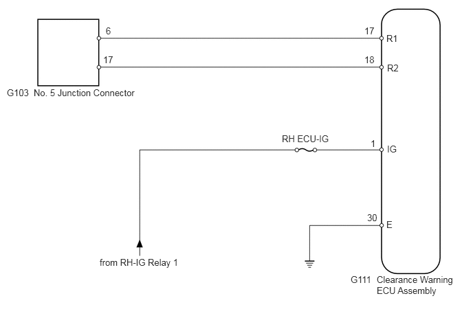
C358385E02
0.51,1.323 3.146,1.552 2.635,0.229 10 false No. 5 Junction Connector 0.104,1.323 0.49,1.49 0.385,0.167 10 false G103 5.313,4.156 5.74,4.313 0.427,0.156 10 false G111 5.708,4.156 6.958,4.625 1.25,0.469 10 false Clearance Warning ECU Assembly 5.854,0.5 6.25,0.667 0.396,0.167 10 false R1 5.865,0.948 6.26,1.115 0.396,0.167 10 false R2 5.865,2.177 6.115,2.333 0.25,0.156 10 false IG 5.854,3.323 6.188,3.49 0.333,0.167 10 false E 4.271,2.021 5.042,2.188 0.771,0.167 10 false RH ECU-IG 1.51,3.896 2.844,4.156 1.333,0.26 10 false from RH-IG Relay 1 1.604,0.385 1.792,0.542 0.188,0.156 10 false 6 1.563,0.823 1.771,0.979 0.208,0.156 10 false 17 5.521,0.385 5.698,0.604 0.177,0.219 10 false 17 5.521,0.823 5.698,1.042 0.177,0.219 10 false 18 5.615,2.094 5.792,2.313 0.177,0.219 10 false 1 5.563,3.219 5.927,3.406 0.365,0.188 10 false 30

CAUTION / NOTICE / HINT

NOTICE:

Turn the engine switch off before measuring the resistances of the main wire and the branch wire.


HINT:

Operating the engine switch, any switches or any doors triggers related ECU and sensor communication with the CAN, which causes resistance variation.


PROCEDURE
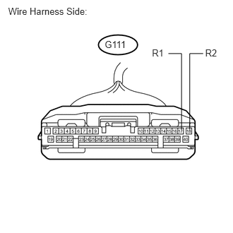
1.CHECK FOR OPEN IN CAN BUS WIRES (CLEARANCE WARNING ECU ASSEMBLY BRANCH WIRE)
a.
U189572E01
2.242,0.703 2.472,0.902 0.230,0.200 10 R1 3.027,0.698 3.257,0.898 0.230,0.200 10 R2 2.678,1.91 2.678,0.79 2.678,0.79 2.484,0.79 false 2.799,1.91 2.799,0.79 2.799,0.79 2.997,0.79 false 1.545,0.57 2.039,0.751 0.494,0.181 10 G111 0.121,0.087 1.406,0.261 1.286,0.174 10 Wire Harness Side:

Disconnect the G111 clearance warning ECU assembly connector.


b.

Measure the resistance of the wire harness side connector.

Standard resistance:
Tester Connection Condition Specified Condition
G111-17 (R1) - G111-18 (R2) Engine switch off 54 to 69 Ω


OK

2.CHECK WIRE HARNESS (CLEARANCE WARNING ECU ASSEMBLY - BATTERY AND BODY GROUND)

NG

REPAIR OR REPLACE CAN BRANCH WIRE CONNECTED TO CLEARANCE WARNING ECU ASSEMBLY (R1, R2)

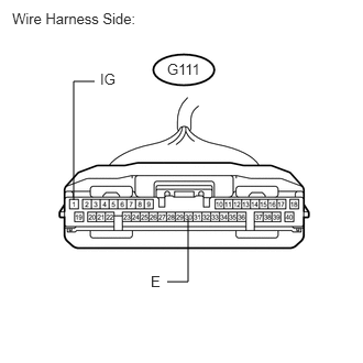
2.CHECK WIRE HARNESS (CLEARANCE WARNING ECU ASSEMBLY - BATTERY AND BODY GROUND)
a.
U189573E02
1.781,2.073 1.781,2.667 1.781,2.667 1.583,2.667 false 0.698,1.896 0.698,0.771 0.698,0.771 0.896,0.771 false 1.427,2.583 1.656,2.781 0.229,0.198 10 false E 0.948,0.667 1.177,0.865 0.229,0.198 10 false IG 1.583,0.573 2.073,0.75 0.49,0.177 10 false G111 0.115,0.094 1.396,0.271 1.281,0.177 10 false Wire Harness Side:

Measure the resistance of the wire harness side connector.

Standard resistance:
Tester Connection Specified Condition
G111-30 (E) - Body ground Below 1 Ω


b.

Measure the voltage of the wire harness side connector.

Standard voltage:
Tester Connection Condition Specified Condition
G111-1 (IG) - Body ground Engine switch on (IG) 11 to 14 V


OK

REPLACE CLEARANCE WARNING ECU ASSEMBLY

NG

REPAIR OR REPLACE HARNESS OR CONNECTOR