RM24M0E
_57
Power Source / Network
_059598
CAN COMMUNICATION
_0292257
CAN COMMUNICATION SYSTEM
J
CAN COMMUNICATION CAN COMMUNICATION SYSTEM Combination Meter ECU Communication Stop Mode
DESCRIPTION
| Detection Item | Symptom | Trouble Area |
|---|---|---|
| COMBINATION METER ECU COMMUNICATION STOP MODE | When either condition below is met:
·
Combination Meter assembly is not displayed on "BUS CHECK" screen of intelligent tester ·
Applies to "COMBINATION METER ECU COMMUNICATION STOP MODE" in "DTC COMBINATION TABLE" |
·
Power source or inside combination meter ECU ·
Combination meter ECU branch wire and connector ·
Combination meter ECU |
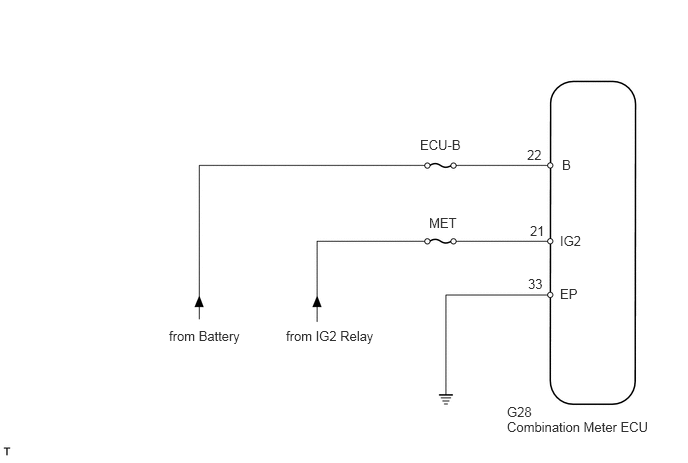
WIRING DIAGRAM
5.281,4.365 6.875,4.708
1.594,0.344
10
false
Combination Meter ECU
5.854,1.635 6.01,1.844
0.156,0.208
10
false
B
5.833,2.427 6.115,2.583
0.281,0.156
10
false
IG2
5.833,2.979 6.073,3.156
0.24,0.177
10
false
EP
4.375,1.427 4.885,1.594
0.51,0.167
10
false
ECU-B
4.469,2.24 4.823,2.427
0.354,0.188
10
false
MET
2.979,3.417 3.979,3.604
1,0.188
10
false
from IG2 Relay
1.76,3.417 2.594,3.615
0.833,0.198
10
false
from Battery
5.49,1.531 5.677,1.688
0.188,0.156
10
false
22
5.521,2.323 5.708,2.479
0.188,0.156
10
false
21
5.5,2.875 5.688,3.031
0.188,0.156
10
false
33
5.281,4.208 5.74,4.406
0.458,0.198
10
false
G28
CAUTION / NOTICE / HINT
- NOTICE:
-
Turn the ignition switch off before measuring the resistances of the main wire and the branch wire.
- HINT:
-
Operating the ignition switch, any switches or any doors triggers related ECU and sensor communication with the CAN, which causes resistance variation.
PROCEDURE
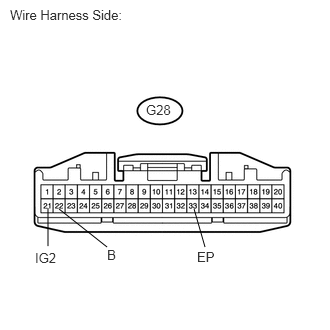
1.CHECK WIRE HARNESS (COMBINATION METER ECU - BATTERY AND BODY GROUND)
0.5,2.167 0.5,2.563
false
0.615,2.177 1.115,2.573
false
2.021,2.177 2.135,2.573
false
0.104,0.073 1.542,0.219
1.438,0.146
10
false
Wire Harness Side:
1.521,1.063 1.885,1.24
0.365,0.177
10
false
G28
0.365,2.604 0.646,2.792
0.281,0.188
10
false
IG2
2.052,2.594 2.281,2.781
0.229,0.188
10
false
EP
1.115,2.573 1.271,2.76
0.156,0.188
10
false
B
a.
Disconnect the G28 combination meter ECU connector.
b.
Measure the resistance of the wire harness side connector.
- Standard resistance:
Tester Connection Specified Condition G28-33 (EP) - Body ground Below 1 Ω
c.
Measure the voltage of the wire harness side connector.
- Standard voltage:
Tester Connection Condition Specified Condition G28-22 (B) - Body ground Always 10 to 14 V G28-21 (IG2) - Body ground Ignition switch on (IG) 10 to 14 V
OK
REPLACE COMBINATION METER ASSEMBLY (COMBINATION METER ECU)
NG
REPAIR OR REPLACE HARNESS OR CONNECTOR