CAN COMMUNICATION CAN COMMUNICATION SYSTEM CAN Main Wire for Disconnection (RHD Models)
DESCRIPTION
There may be an open circuit in the CAN main wire and/or the DLC3 branch wire when the resistance between terminals 6 (CANH) and 14 (CANL) of the DLC3 is 70 Ω or more.
| Symptom | Trouble Area |
|---|---|
| Resistance between terminals 6 (CANH) and 14 (CANL) of DLC3 is 70 Ω or more. | ·
CAN main wire and connector ·
No. 2 CAN junction connector LH ·
No. 2 junction connector ·
No. 4 junction connector ·
No. 5 junction connector ·
ECM ·
Combination meter ECU |
WIRING DIAGRAM
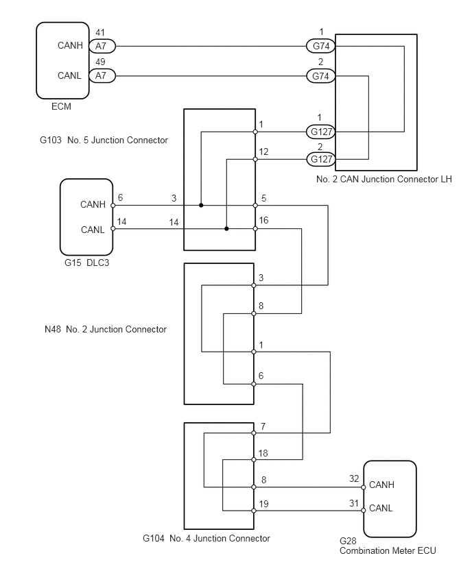
CAUTION / NOTICE / HINT
- NOTICE:
-
Turn the engine switch off before measuring the resistances of the main wire and the branch wire.
- HINT:
-
Operating the engine switch, any switches or any doors triggers related ECU and sensor communication with the CAN, which causes resistance variation.
PROCEDURE
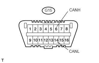
Measure the resistance of the DLC3.
| Tester Connection | Condition | Measured Resistance | Proceed to |
|---|---|---|---|
| G15-6 (CANH) - G15-14 (CANL) | Engine switch off | 108 to 132 Ω | A |
| G15-6 (CANH) - G15-14 (CANL) | Engine switch off | 133 Ω or more | B |
- NOTICE:
-
When the measured value is 133 Ω or more and a CAN communication system diagnostic trouble code is output, there may be a fault besides disconnection of the DLC3 branch wire. For that reason, troubleshooting should be performed again from "HOW TO PROCEED WITH TROUBLESHOOTING" (see page Power Source / Network>CAN COMMUNICATION>CAN COMMUNICATION SYSTEM>HOW TO PROCEED WITH TROUBLESHOOTING) after repairing the trouble area.
A
B
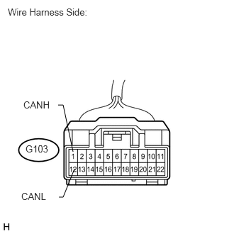
Disconnect the G103 No. 5 junction connector.
Measure the resistance of the wire harness side connector.
- Standard resistance:
Tester Connection Condition Specified Condition G103-1 (CANH) - G103-12 (CANL) Engine switch off 108 to 132 Ω
OK
NG
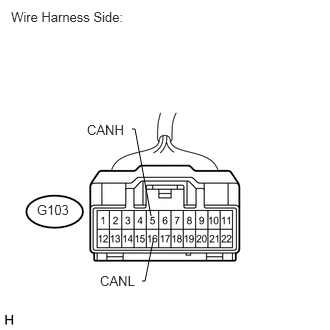
Measure the resistance of the wire harness side connector.
- Standard resistance:
Tester Connection Condition Specified Condition G103-5 (CANH) - G103-16 (CANL) Engine switch off 108 to 132 Ω
OK
NG
Reconnect the G103 No. 5 junction connector.
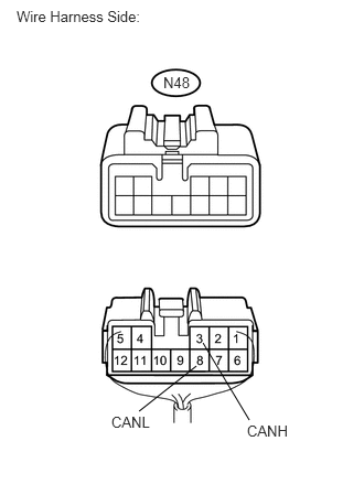
Disconnect the N48 No. 2 junction connector.
Measure the resistance of the wire harness side connector.
- Standard resistance:
Tester Connection Condition Specified Condition N48-3 (CANH) - N48-8 (CANL) Engine switch off 108 to 132 Ω
OK
NG
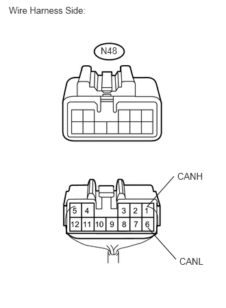
Measure the resistance of the wire harness side connector.
- Standard resistance:
Tester Connection Condition Specified Condition N48-1 (CANH) - N48-6 (CANL) Engine switch off 108 to 132 Ω
OK
NG
Reconnect the N48 No. 2 junction connector.
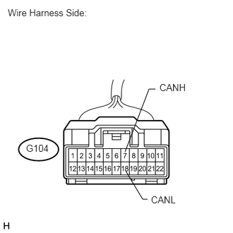
Disconnect the G104 No. 4 junction connector.
Measure the resistance of the wire harness side connector.
- Standard resistance:
Tester Connection Condition Specified Condition G104-7 (CANH) - G104-18 (CANL) Engine switch off 108 to 132 Ω
OK
NG
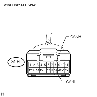
Measure the resistance of the wire harness side connector.
- Standard resistance:
Tester Connection Condition Specified Condition G104-8 (CANH) - G104-19 (CANL) Engine switch off 108 to 132 Ω
OK
NG
Reconnect the G104 No. 4 junction connector.
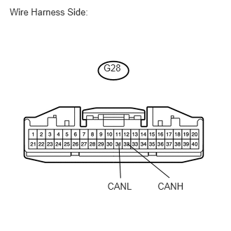
Disconnect the G28 combination meter ECU connector.
Measure the resistance of the wire harness side connector.
- Standard resistance:
Tester Connection Condition Specified Condition G28-32 (CANH) - G28-31 (CANL) Engine switch off 108 to 132 Ω
OK
NG
Reconnect the G103 No. 5 junction connector.
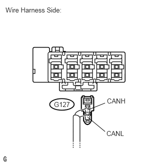
Disconnect the G127 No. 2 CAN junction connector LH connector.
Measure the resistance of the wire harness side connector.
- Standard resistance:
Tester Connection Condition Specified Condition G127-1 (CANH) - G127-2 (CANL) Engine switch off 108 to 132 Ω
OK
NG
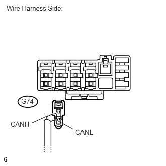
Disconnect the G74 No. 2 CAN junction connector LH connector.
Measure the resistance of the wire harness side connector.
- Standard resistance:
Tester Connection Condition Specified Condition G74-1 (CANH) - G74-2 (CANL) Engine switch off 108 to 132 Ω
OK
NG
Reconnect the G74 No. 2 CAN junction connector LH connector.
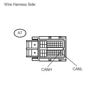
Disconnect the A7 ECM connector.
Measure the resistance of the wire harness side connector.
- Standard resistance:
Tester Connection Condition Specified Condition A7-41 (CANH) - A7-49 (CANL) Engine switch off 108 to 132 Ω
OK
NG