Home › Power Source / Network › CAN COMMUNICATION › CAN COMMUNICATION SYSTEM › 2013.04–2016.05
RM24M0E _57 Power Source / Network _059598 CAN COMMUNICATION _0292257 CAN COMMUNICATION SYSTEM C

CAN COMMUNICATION  CAN COMMUNICATION SYSTEM  B2326  CAN MS Bus Line Communication Malfunction  


DESCRIPTION

DTC No. Detection Item Trouble Area
B2326 CAN MS Bus Line Communication Malfunction
·

CAN MS bus circuit

·

Certification ECU branch wire and connector

·

Power slide door ECU RH branch wire and connector

·

Power slide door ECU LH branch wire and connector

·

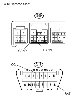
Power back door ECU branch wire and connector

·

Main body ECU main wire and connector

·

Combination meter ECU main wire and connector

·

Main body ECU

·

Combination meter ECU

·

No. 2 junction connector

·

No. 3 junction connector

·

No. 2 CAN junction connector RH

·

Power slide door ECU RH*1

·

Power slide door ECU LH*1

·

Power back door ECU*2

·

Certification ECU


HINT:

*1: w/ Power slide door system

*2: w/ power back door system


WIRING DIAGRAM
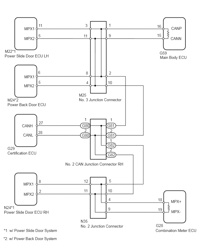
C137764E08
0.167,1.927 2.104,2.26 1.938,0.333 10 false Power Slide Door ECU LH 0.875,0.948 1.292,1.094 0.417,0.146 10 false MPX1 0.875,1.302 1.292,1.448 0.417,0.146 10 false MPX2 0.271,3.677 1.719,4.01 1.448,0.333 10 false Power Back Door ECU 0.271,5.417 1.354,5.75 1.083,0.333 10 false Certification ECU 0.146,7.542 1.813,7.875 1.667,0.333 10 false Power Slide Door ECU RH 5.76,1.979 6.792,2.313 1.031,0.333 10 false Main Body ECU 5.604,8.198 7.135,8.531 1.531,0.333 10 false Combination Meter ECU 2.844,3.5 4.448,3.833 1.604,0.333 10 false No. 3 Junction Connector 3.021,6.771 3.208,6.927 0.188,0.156 10 false 11 3.927,6.417 4.042,6.573 0.115,0.156 10 false 5 1.385,0.833 1.573,0.99 0.188,0.156 10 false 11 3.073,0.833 3.24,1 0.167,0.167 10 false 3 3.917,0.823 4.031,0.979 0.115,0.156 10 false 1 3.917,1.198 4.031,1.354 0.115,0.156 10 false 9 5.656,0.865 5.844,1.021 0.188,0.156 10 false 16 5.656,1.188 5.844,1.344 0.188,0.156 10 false 15 6.167,0.938 6.583,1.094 0.417,0.156 10 false CANP 6.146,1.302 6.563,1.458 0.417,0.156 10 false CANN 0.875,2.677 1.292,2.823 0.417,0.146 10 false MPX1 0.865,3 1.281,3.146 0.417,0.146 10 false MPX2 1.375,2.521 1.479,2.677 0.104,0.156 10 false 6 1.385,1.198 1.5,1.354 0.115,0.156 10 false 5 3.094,2.542 3.208,2.698 0.115,0.156 10 false 8 3.104,2.885 3.219,3.042 0.115,0.156 10 false 4 3.927,2.542 4.042,2.698 0.115,0.156 10 false 2 3.885,6.771 4.073,6.927 0.188,0.156 10 false 10 2.354,5.813 4.542,5.969 2.188,0.156 10 false No. 2 CAN Junction Connector RH 2.906,8.042 4.521,8.396 1.615,0.354 10 false No. 2 Junction Connector 0.792,4.438 1.208,4.604 0.417,0.167 10 false CANH 0.833,4.771 1.25,4.938 0.417,0.167 10 false CANL 1.396,4.333 1.583,4.49 0.188,0.156 10 false 27 1.375,4.677 1.563,4.833 0.188,0.156 10 false 28 3.969,4.219 4.083,4.375 0.115,0.156 10 false 1 3.958,4.969 4.073,5.125 0.115,0.156 10 false 1 3.958,5.302 4.073,5.458 0.115,0.156 10 false 2 3.969,4.615 4.083,4.771 0.115,0.156 10 false 2 3.042,4.208 3.156,4.365 0.115,0.156 10 false 1 1.406,6.792 1.521,6.948 0.115,0.156 10 false 2 2.948,4.781 3.24,4.927 0.292,0.146 10 false G80 2.958,4.427 3.25,4.573 0.292,0.146 10 false G80 3.865,4.427 4.156,4.573 0.292,0.146 10 false G81 3.875,4.781 4.167,4.927 0.292,0.146 10 false G81 3.875,5.135 4.167,5.281 0.292,0.146 10 false G82 3.885,5.479 4.177,5.625 0.292,0.146 10 false G82 0.844,6.531 1.26,6.677 0.417,0.146 10 false MPX1 0.854,6.896 1.281,7.073 0.427,0.177 10 false MPX2 1.396,6.438 1.51,6.583 0.115,0.146 10 false 8 3.042,4.604 3.156,4.75 0.115,0.146 10 false 2 3.021,6.427 3.198,6.573 0.177,0.146 10 false 12 3.01,1.208 3.188,1.354 0.177,0.146 10 false 11 1.385,2.875 1.563,3.021 0.177,0.146 10 false 5 3.885,2.885 4.063,3.031 0.177,0.146 10 false 10 3.906,7.083 4.083,7.229 0.177,0.146 10 false 4 3.896,7.427 4.073,7.573 0.177,0.146 10 false 9 6.156,7.156 6.76,7.385 0.604,0.229 10 false MPX+ 6.167,7.521 6.844,7.802 0.677,0.281 10 false MPX- 5.688,7.094 5.865,7.24 0.177,0.146 10 false 18 5.688,7.448 5.865,7.594 0.177,0.146 10 false 19 0.135,8.198 2.188,8.375 2.052,0.177 10 false *1: w/ Power Slide Door System 0.125,8.49 2.688,8.667 2.563,0.177 10 false *2: w/ Power Back Door System 2.906,7.865 3.271,8.125 0.365,0.26 10 false N35 0.146,7.375 0.563,7.521 0.417,0.146 10 false N24*1 5.615,8.021 5.979,8.281 0.365,0.26 10 false G28 0.271,5.25 0.688,5.417 0.417,0.167 10 false G29 0.271,3.51 0.708,3.667 0.438,0.156 10 false M24*2 2.844,3.333 3.135,3.479 0.292,0.146 10 false M25 0.177,1.76 0.615,1.917 0.438,0.156 10 false M22*1 5.75,1.823 6.167,1.979 0.417,0.156 10 false G59

PROCEDURE

1.CHECK CAN BUS LINE (MAIN WIRE FOR DISCONNECTION, BUS LINES FOR SHORT CIRCUIT)
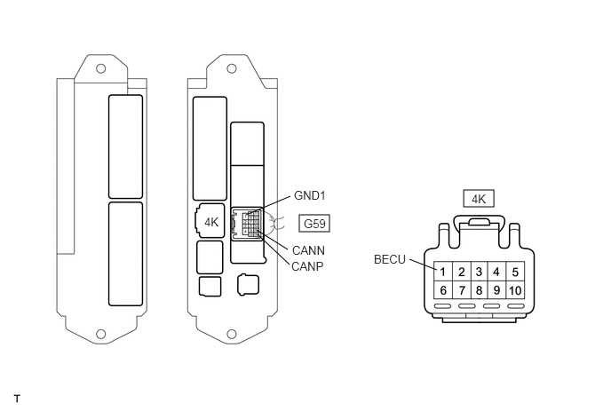
C367887E02
3.51,2.521 3.865,2.719 0.354,0.198 5.438,2.229 5.792,2.427 0.354,0.198 2.885,2.521 3.406,2.302 false 3.01,2.698 3.375,2.927 false 3.021,2.75 3.396,3.104 false 4.802,3.042 5.125,3.167 false 2.396,2.521 2.708,2.719 0.313,0.198 10 false 4K 3.448,2.208 3.76,2.406 0.313,0.198 10 false GND1 3.427,2.854 3.938,3.052 0.51,0.198 10 false CANN 3.417,3.042 3.927,3.24 0.51,0.198 10 false CANP 3.563,2.542 3.875,2.74 0.313,0.198 10 false G59 4.385,2.958 4.896,3.156 0.51,0.198 10 false BECU 5.531,2.25 5.844,2.448 0.313,0.198 10 false 4K

a.

Remove the main body ECU with the connector connected.


b.

Disconnect the 4K ECU connectors.


c.

Measure the resistance of the wire harness side connectors.

Standard resistance:
Tester Connection Specified Condition Resistance of Malfunction
G59-16 (CANP) - G59-15 (CANN) 54 to 69 Ω Below 53 Ω: Short in line
70 Ω or more: Open in CAN main bus line
G59-16 (CANP) - 4K-1 (BECU) 6 kΩ or more Below 6 kΩ: +B short
G59-15 (CANN) - 4K-1 (BECU) 6 kΩ or more Below 6 kΩ: +B short
G59-16 (CANP) - G59-1 (GND1) 200 Ω or more Below 200 Ω: Ground short
G59-15 (CANN) - G59-1 (GND1) 200 Ω or more Below 200 Ω: Ground short


Result
Result Proceed to
NG
- Open in CAN main bus line
A
NG
- Short in line
- +B short
- Ground short
B
OK C


A

2.CHECK CAN MAIN WIRE FOR DISCONNECTION (NO. 2 CAN JUNCTION CONNECTOR RH - MAIN BODY ECU)

B

15.CHECK CAN BUS LINES FOR SHORT (NO. 3 JUNCTION CONNECTOR SIDE)

C

41.CHECK CAN BUS LINE FOR DISCONNECTION
2.CHECK CAN MAIN WIRE FOR DISCONNECTION (NO. 2 CAN JUNCTION CONNECTOR RH - MAIN BODY ECU)
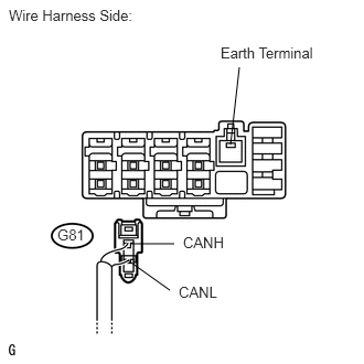
U189247E02
1.24,2.302 1.646,2.302 false 1.208,2.458 1.604,2.74 false 2.177,1.365 2.26,0.635 false 0.083,0.063 1.552,0.208 1.469,0.146 10 false Wire Harness Side: 0.542,2.135 0.833,2.292 0.292,0.156 10 false G81 1.729,2.208 2.156,2.365 0.427,0.156 10 false CANH 1.688,2.677 2.115,2.833 0.427,0.156 10 false CANL 2.083,0.417 3.021,0.583 0.938,0.167 10 false Earth Terminal

a.

Disconnect the G81 No. 2 CAN junction connector RH.


b.

Measure the resistance of the wire harness side connector.

Standard resistance:
Tester Connection Condition Specified Condition
G81-1 (CANH) - G81-2 (CANL) Engine switch off 108 to 132 Ω


OK

3.CONNECT CONNECTOR

NG

5.CONNECT CONNECTOR
3.CONNECT CONNECTOR
a.

Reconnect the G81 No. 2 CAN junction connector RH.


NEXT
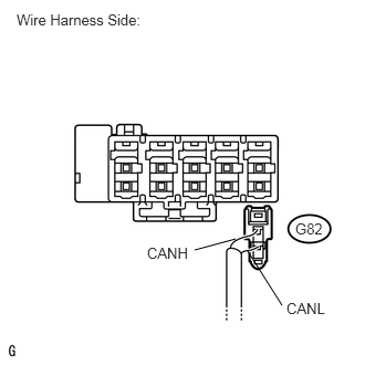
4.CHECK CAN MAIN WIRE FOR DISCONNECTION (NO. 2 CAN JUNCTION CONNECTOR RH - COMBINATION METER ECU)
a.
U189251E02
2.219,2.25 1.833,2.354 false 2.333,2.365 2.656,2.875 false 0.156,0.104 1.521,0.281 1.365,0.177 10 false Wire Harness Side: 2.781,2.073 3.083,2.229 0.302,0.156 10 false G82 1.385,2.302 1.802,2.458 0.417,0.156 10 false CANH 2.698,2.823 3.115,2.979 0.417,0.156 10 false CANL

Disconnect the G82 No. 2 CAN junction connector RH.


b.

Measure the resistance of the wire harness side connector.

Standard resistance:
Tester Connection Condition Specified Condition
G82-1 (CANH) - G82-2 (CANL) Engine switch off 108 to 132 Ω


OK

REPLACE NO. 2 CAN JUNCTION CONNECTOR RH

NG

10.CONNECT CONNECTOR
5.CONNECT CONNECTOR
a.

Reconnect the G82 No. 2 CAN junction connector RH.


NEXT
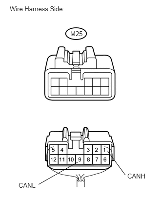
6.CHECK CAN MAIN WIRE FOR DISCONNECTION (NO. 3 JUNCTION CONNECTOR - MAIN BODY ECU)
a.
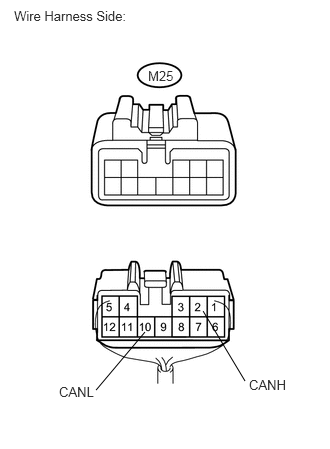
U189079E02
1.667,3.458 0.823,3.938 false 2.292,3.219 2.677,3.74 false 0.208,0.104 1.583,0.26 1.375,0.156 10 false Wire Harness Side: 1.5,0.635 1.813,0.802 0.313,0.167 10 false M25 0.396,3.875 0.823,4.052 0.427,0.177 10 false CANL 2.719,3.677 3.146,3.854 0.427,0.177 10 false CANH

Disconnect the M25 No. 3 junction connector.


b.

Measure the resistance of the wire harness side connectors.

Standard resistance:
Tester Connection Condition Specified Condition
M25-1 (CANH) - M25-9 (CANL) Engine switch off 108 to 132 Ω


OK

7.CHECK CAN MAIN WIRE FOR DISCONNECTION (NO. 3 JUNCTION CONNECTOR - NO. 2 CAN JUNCTION CONNECTOR RH)

NG

8.CONNECT CONNECTOR
7.CHECK CAN MAIN WIRE FOR DISCONNECTION (NO. 3 JUNCTION CONNECTOR - NO. 2 CAN JUNCTION CONNECTOR RH)
a.
U189080E02
1.51,3.458 1,4.063 false 2.115,3.24 2.552,3.969 false 0.146,0.083 1.448,0.26 1.302,0.177 10 false Wire Harness Side: 1.542,0.708 1.865,0.875 0.323,0.167 10 false M25 0.615,4 1.052,4.156 0.438,0.156 10 false CANL 2.594,3.927 3.031,4.083 0.438,0.156 10 false CANH

Measure the resistance of the wire harness side connectors.

Standard resistance:
Tester Connection Condition Specified Condition
M25-2 (CANH) - M25-10 (CANL) Engine switch off 108 to 132 Ω


OK

REPLACE NO. 3 JUNCTION CONNECTOR

NG

REPAIR OR REPLACE CAN MAIN WIRE OR CONNECTOR (NO. 3 JUNCTION CONNECTOR - NO. 2 CAN JUNCTION CONNECTOR RH)

8.CONNECT CONNECTOR
a.

Reconnect the M25 No. 3 junction connector.


NEXT
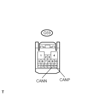
9.CHECK CAN MAIN WIRE FOR DISCONNECTION (MAIN BODY ECU - NO. 3 JUNCTION CONNECTOR)
a.
U189298E02
2.021,2.427 2.344,2.792 false 1.885,2.427 1.521,2.823 false 1.573,1.104 1.854,1.25 0.281,0.146 10 false G59 2.156,2.802 2.583,2.958 0.427,0.156 10 false CANP 1.313,2.844 1.74,3 0.427,0.156 10 false CANN

Disconnect the G59 main body ECU connector.


b.

Measure the resistance of the wire harness side connector.

Standard resistance:
Tester Connection Condition Specified Condition
G59-16 (CANP) - G59-15 (CANN) Engine switch off 108 to 132 Ω


OK

REPLACE MAIN BODY ECU

NG

REPAIR OR REPLACE CAN MAIN WIRE CONNECTED TO MAIN BODY ECU (MAIN BODY ECU - NO. 3 JUNCTION CONNECTOR)

10.CONNECT CONNECTOR
a.

Reconnect the G82 No. 2 CAN junction connector RH.


NEXT
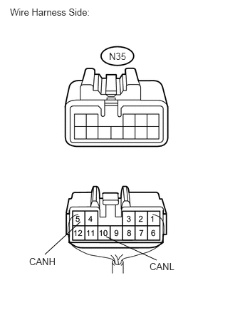
11.CHECK CAN MAIN WIRE FOR DISCONNECTION (NO. 2 JUNCTION CONNECTOR - NO. 2 CAN JUNCTION CONNECTOR RH)
a.
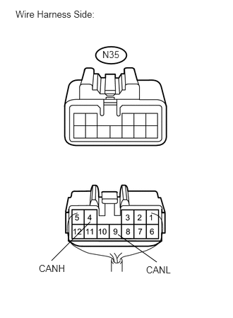
U189083E02
1.177,3.24 0.656,3.719 false 1.552,3.458 2.292,3.802 false 0.146,0.094 1.688,0.281 1.542,0.188 10 false Wire Harness Side: 1.594,0.74 1.885,0.896 0.292,0.156 10 false N35 0.427,3.74 0.865,3.885 0.438,0.146 10 false CANH 2.188,3.813 2.625,3.958 0.438,0.146 10 false CANL

Disconnect the N35 No. 2 junction connector.


b.

Measure the resistance of the wire harness side connectors.

Standard resistance:
Tester Connection Condition Specified Condition
N35-5 (CANH) - N35-10 (CANL) Engine switch off 108 to 132 Ω


OK

12.CHECK CAN MAIN WIRE FOR DISCONNECTION (NO. 2 JUNCTION CONNECTOR - COMBINATION METER ECU)

NG

REPAIR OR REPLACE CAN MAIN WIRE OR CONNECTOR (NO. 2 JUNCTION CONNECTOR - NO. 2 CAN JUNCTION CONNECTOR RH)

12.CHECK CAN MAIN WIRE FOR DISCONNECTION (NO. 2 JUNCTION CONNECTOR - COMBINATION METER ECU)
a.
U189084E02
1.333,3.26 0.76,3.833 false 1.74,3.448 2.313,3.854 false 0.229,0.125 1.604,0.281 1.375,0.156 10 false Wire Harness Side: 1.51,0.719 1.844,0.896 0.333,0.177 10 false N35 0.573,3.865 1,4.01 0.427,0.146 10 false CANH 2.156,3.885 2.583,4.031 0.427,0.146 10 false CANL

Measure the resistance of the wire harness side connectors.

Standard resistance:
Tester Connection Condition Specified Condition
N35-4 (CANH) - N35-9 (CANL) Engine switch off 108 to 132 Ω


OK

REPLACE NO. 2 JUNCTION CONNECTOR

NG

13.CONNECT CONNECTOR
a.

Reconnect the N35 No. 2 junction connector.


NEXT
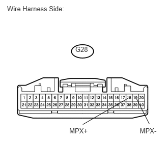
14.CHECK CAN MAIN WIRE FOR DISCONNECTION (COMBINATION METER ECU - NO. 2 JUNCTION CONNECTOR)
a.
U188996E01
0.144,0.099 1.587,0.283 1.443,0.184 10 Wire Harness Side: 1.54,0.929 1.849,1.126 0.309,0.198 10 G28 1.418,2.595 1.851,2.765 0.433,0.170 10 MPX+ 2.861,2.595 3.294,2.765 0.434,0.170 10 MPX- 2.614,2.014 1.694,2.547 false 2.794,2.022 3.056,2.538 false

Disconnect the G28 combination meter ECU connector.


b.

Measure the resistance of the wire harness side connector.

Standard resistance:
Tester Connection Condition Specified Condition
G28-18 (MPX+) - G28-19 (MPX-) Engine switch off 108 to 132 Ω


OK

REPLACE COMBINATION METER ASSEMBLY (COMBINATION METER ECU)

NG

REPAIR OR REPLACE CAN MAIN WIRE CONNECTED TO COMBINATION METER ASSEMBLY (COMBINATION METER ECU - NO. 2 JUNCTION CONNECTOR)

15.CHECK CAN BUS LINES FOR SHORT (NO. 3 JUNCTION CONNECTOR SIDE)
a.
U189417E02
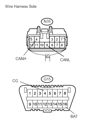
1.427,1.792 1.063,2.125 false 1.563,1.781 1.927,2.104 false 2.385,3.688 2.854,3.979 false 1.625,3.208 0.76,2.854 false 0.156,0.083 1.542,0.271 1.385,0.188 10 false Wire Harness Side: 1.583,0.594 1.875,0.76 0.292,0.167 10 false G59 0.802,2.135 1.219,2.292 0.417,0.156 10 false CANP 1.906,2.104 2.323,2.26 0.417,0.156 10 false CANN 1.563,2.74 1.854,2.906 0.292,0.167 10 false G15 2.854,4.01 3.167,4.177 0.313,0.167 10 false BAT 0.49,2.74 0.74,2.896 0.25,0.156 10 false CG

Remove the instrument panel junction block LH with the connector.


b.

Disconnect the G81 No. 2 CAN junction connector RH.


c.

Measure the resistance of the wire harness side connectors.

Standard resistance:
Tester Connection Specified Condition
G59-16 (CANP) - G59-15 (CANN) 108 to 132 Ω
G59-16 (CANP) - G15-4 (CG) 200 Ω or more
G59-15 (CANN) - G15-4 (CG) 200 Ω or more
G59-16 (CANP) - G15-16 (BAT) 6 kΩ or more
G59-15 (CANN) - G15-16 (BAT) 6 kΩ or more


NG

16.CHECK CAN BUS LINES FOR SHORT (NO. 3 JUNCTION CONNECTOR - NO. 2 CAN JUNCTION CONNECTOR RH)

OK

27.CONNECT CONNECTOR
16.CHECK CAN BUS LINES FOR SHORT (NO. 3 JUNCTION CONNECTOR - NO. 2 CAN JUNCTION CONNECTOR RH)
a.
U189287E02
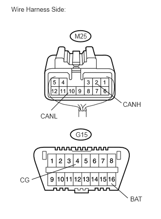
1.615,3.51 0.677,3.833 false 2.375,3.917 2.729,4.229 false 2.083,1.802 2.594,2.198 false 1.458,1.979 1.094,2.354 false 0.24,0.115 1.615,0.292 1.375,0.177 10 false Wire Harness Side: 1.594,0.688 1.906,0.833 0.313,0.146 10 false M25 1.615,2.792 1.927,2.938 0.313,0.146 10 false G15 2.625,2.146 3.052,2.302 0.427,0.156 10 false CANH 0.865,2.396 1.292,2.552 0.427,0.156 10 false CANL 0.427,3.76 0.656,3.906 0.229,0.146 10 false CG 2.781,4.167 3.073,4.323 0.292,0.156 10 false BAT

Measure the resistance of the wire harness side connectors.

Standard resistance:
Tester Connection Specified Condition
M25-2 (CANH) - M25-10 (CANL) 108 to 132 Ω
M25-2 (CANH) - G15-4 (CG) 200 Ω or more
M25-10 (CANL) - G15-4 (CG) 200 Ω or more
M25-2 (CANH) - G15-16 (BAT) 6 kΩ or more
M25-10 (CANL) - G15-16 (BAT) 6 kΩ or more


OK

17.CONNECT CONNECTOR

NG

REPAIR OR REPLACE CAN MAIN WIRE OR CONNECTOR (NO. 3 JUNCTION CONNECTOR - NO. 2 CAN JUNCTION CONNECTOR RH)

17.CONNECT CONNECTOR
a.

Reconnect the G81 No. 2 CAN junction connector RH.


NEXT

18.CHECK CAN BUS LINES FOR SHORT (NO. 3 JUNCTION CONNECTOR - POWER SLIDE DOOR ECU LH)
NOTICE:

For vehicles without power slide door system, go to "CAN BUS LINES FOR SHORT (NO. 3 JUNCTION CONNECTOR - POWER BACK DOOR ECU)"
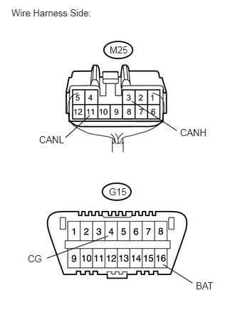

a.
U189253E02
1.927,1.479 2.583,1.906 false 1.313,1.688 0.958,2.01 false 1.583,3.448 0.688,3.771 false 2.385,3.865 2.813,4.135 false 1.594,2.719 1.896,2.917 0.302,0.198 10 false G15 1.604,0.646 1.927,0.833 0.323,0.188 10 false M25 2.635,1.854 3.063,2.01 0.427,0.156 10 false CANH 0.573,1.958 1,2.115 0.427,0.156 10 false CANL 2.865,4.094 3.156,4.25 0.292,0.156 10 false BAT 0.406,3.698 0.635,3.854 0.229,0.156 10 false CG 0.167,0.104 1.604,0.271 1.438,0.167 10 false Wire Harness Side:

Disconnect the M25 No. 3 junction connector.


b.

Measure the resistance of the wire harness side connectors.

Result
Tester Connection Condition Measured Resistance Proceed to
M25-3 (CANH) - M25-11 (CANL) Engine switch off 1 Ω or more OK
M25-3 (CANH) - M25-11 (CANL) Engine switch off Below 1 Ω NG
M25-3 (CANH) - G15-4 (CG) Engine switch off 1 Ω or more OK
M25-11 (CANL) - G15-4 (CG) Engine switch off 1 Ω or more OK
M25-3 (CANH) - G15-4 (CG) Engine switch off Below 1 Ω NG
M25-11 (CANL) - G15-4 (CG) Engine switch off Below 1 Ω NG
M25-3 (CANH) - G15-16 (BAT) Engine switch off 1 Ω or more OK
M25-11 (CANL) - G15-16 (BAT) Engine switch off 1 Ω or more OK
M25-3 (CANH) - G15-16 (BAT) Engine switch off Below 1 Ω NG
M25-11 (CANL) - G15-16 (BAT) Engine switch off Below 1 Ω NG


OK

19.CHECK CAN BUS LINES FOR SHORT (NO. 3 JUNCTION CONNECTOR - POWER BACK DOOR ECU)

NG

21.CONNECT CONNECTOR
19.CHECK CAN BUS LINES FOR SHORT (NO. 3 JUNCTION CONNECTOR - POWER BACK DOOR ECU)
NOTICE:
·

For vehicle w/ Power Back Door System:

Perform the procedures below.

·

For vehicle w/o Power Back Door System:

Go to "CHECK CAN BUS LINES FOR SHORT (NO. 3 JUNCTION CONNECTOR - MAIN BODY ECU)"
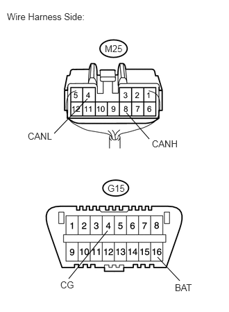


a.
U189254E02
1.896,1.688 2.24,2.083 false 1.313,1.479 0.813,2 false 1.615,3.458 1.031,4.177 false 2.365,3.854 2.698,4.208 false 0.104,0.167 1.458,0.333 1.354,0.167 10 false Wire Harness Side: 1.615,2.74 1.896,2.906 0.281,0.167 10 false G15 1.573,0.646 1.896,0.813 0.323,0.167 10 false M25 2.281,2.073 2.729,2.24 0.448,0.167 10 false CANH 0.417,1.958 0.865,2.125 0.448,0.167 10 false CANL 0.906,4.188 1.167,4.354 0.26,0.167 10 false CG 2.625,4.229 2.938,4.406 0.313,0.177 10 false BAT

Measure the resistance of the wire harness side connectors.

Result
Tester Connection Condition Measured Resistance Proceed to
M25-8 (CANH) - M25-4 (CANL) Engine switch off 1 Ω or more OK
M25-8 (CANH) - M25-4 (CANL) Engine switch off Below 1 Ω NG
M25-8 (CANH) - G15-4 (CG) Engine switch off 1 Ω or more OK
M25-4 (CANL) - G15-4 (CG) Engine switch off 1 Ω or more OK
M25-8 (CANH) - G15-4 (CG) Engine switch off Below 1 Ω NG
M25-4 (CANL) - G15-4 (CG) Engine switch off Below 1 Ω NG
M25-8 (CANH) - G15-16 (BAT) Engine switch off 1 Ω or more OK
M25-4 (CANL) - G15-16 (BAT) Engine switch off 1 Ω or more OK
M25-8 (CANH) - G15-16 (BAT) Engine switch off Below 1 Ω NG
M25-4 (CANL) - G15-16 (BAT) Engine switch off Below 1 Ω NG


OK

20.CHECK CAN BUS LINES FOR SHORT (NO. 3 JUNCTION CONNECTOR - MAIN BODY ECU)

NG

23.CONNECT CONNECTOR
20.CHECK CAN BUS LINES FOR SHORT (NO. 3 JUNCTION CONNECTOR - MAIN BODY ECU)
a.
U189255E02
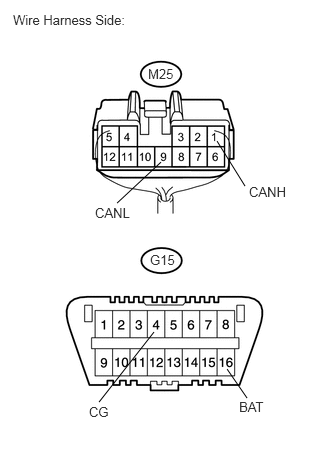
2.26,1.469 2.552,1.938 false 1.677,1.688 1.219,2.115 false 1.604,3.458 1.031,4.188 false 2.365,3.844 2.573,4.146 false 0.135,0.125 1.552,0.292 1.417,0.167 10 false Wire Harness Side: 1.542,0.688 1.844,0.854 0.302,0.167 10 false M25 1.563,2.625 1.865,2.792 0.302,0.167 10 false G15 2.594,1.917 3.042,2.073 0.448,0.156 10 false CANH 0.99,2.135 1.438,2.292 0.448,0.156 10 false CANL 0.927,4.208 1.198,4.375 0.271,0.167 10 false CG 2.49,4.156 2.823,4.323 0.333,0.167 10 false BAT

Measure the resistance of the wire harness side connectors.

Result
Tester Connection Condition Measured Resistance Proceed to
M25-1 (CANH) - M25-9 (CANL) Engine switch off 1 Ω or more OK
M25-1 (CANH) - M25-9 (CANL) Engine switch off Below 1 Ω NG
M25-1 (CANH) - G15-4 (CG) Engine switch off 1 Ω or more OK
M25-9 (CANL) - G15-4 (CG) Engine switch off 1 Ω or more OK
M25-1 (CANH) - G15-4 (CG) Engine switch off Below 1 Ω NG
M25-9 (CANL) - G15-4 (CG) Engine switch off Below 1 Ω NG
M25-1 (CANH) - G15-16 (BAT) Engine switch off 1 Ω or more OK
M25-9 (CANL) - G15-16 (BAT) Engine switch off 1 Ω or more OK
M25-1 (CANH) - G15-16 (BAT) Engine switch off Below 1 Ω NG
M25-9 (CANL) - G15-16 (BAT) Engine switch off Below 1 Ω NG


OK

REPAIR OR REPLACE NO. 3 JUNCTION CONNECTOR

NG

25.CONNECT CONNECTOR
21.CONNECT CONNECTOR
a.

Reconnect the M25 No. 3 junction connector.


NEXT
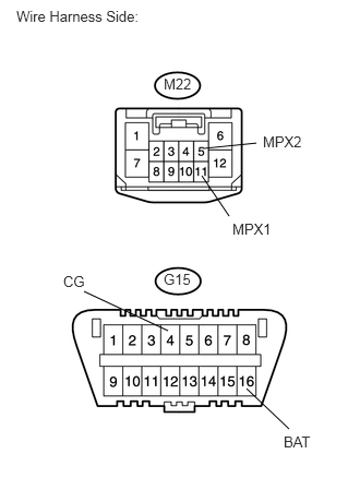
22.CHECK CAN BUS LINES FOR SHORT (POWER SLIDE DOOR ECU LH)
a.
U189418E02
1.927,1.677 2.188,2.063 false 1.938,1.417 2.448,1.365 false 2.354,3.708 2.76,4.094 false 1.604,3.156 0.802,2.781 false 0.156,0.073 1.5,0.24 1.344,0.167 10 false Wire Harness Side: 1.563,0.719 1.885,0.875 0.323,0.156 10 false M22 2.219,2.104 2.635,2.26 0.417,0.156 10 false MPX1 2.51,1.271 2.927,1.427 0.417,0.156 10 false MPX2 1.563,2.583 1.885,2.74 0.323,0.156 10 false G15 2.708,4.135 3.042,4.281 0.333,0.146 10 false BAT 0.604,2.604 0.844,2.781 0.24,0.177 10 false CG

Disconnect the M22 power slide door ECU LH connector.


b.

Measure the resistance of the wire harness side connectors.

Result
Tester Connection Condition Measured Resistance Proceed to
M22-11 (MPX1) - M22-5 (MPX2) Engine switch off 1 Ω or more OK
M22-11 (MPX1) - M22-5 (MPX2) Engine switch off Below 1 Ω NG
M22-11 (MPX1) - G15-4 (CG) Engine switch off 1 Ω or more OK
M22-5 (MPX2) - G15-4 (CG) Engine switch off 1 Ω or more OK
M22-11 (MPX1) - G15-4 (CG) Engine switch off Below 1 Ω NG
M22-5 (MPX2) - G15-4 (CG) Engine switch off Below 1 Ω NG
M22-11 (MPX1) - G15-16 (BAT) Engine switch off 1 Ω or more OK
M22-5 (MPX2) - G15-16 (BAT) Engine switch off 1 Ω or more OK
M22-11 (MPX1) - G15-16 (BAT) Engine switch off Below 1 Ω NG
M22-5 (MPX2) - G15-16 (BAT) Engine switch off Below 1 Ω NG


OK

REPLACE POWER SLIDE DOOR ECU LH

NG

REPAIR OR REPLACE CAN BRANCH WIRE CONNECTED TO POWER SLIDE DOOR ECU LH (CANH, CANL)

23.CONNECT CONNECTOR
a.

Reconnect the M25 No. 3 junction connector.


NEXT
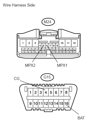
24.CHECK CAN BUS LINES FOR SHORT (POWER BACK DOOR ECU)
a.
U189419E02
1.521,1.635 1.146,2.198 false 1.677,1.635 2.042,2.219 false 2.344,3.719 2.792,4.052 false 1.604,3.188 0.708,2.854 false 0.104,0.094 1.5,0.292 1.396,0.198 10 false Wire Harness Side: 1.552,0.688 1.875,0.854 0.323,0.167 10 false M24 2.021,2.229 2.417,2.385 0.396,0.156 10 false MPX1 0.885,2.229 1.281,2.385 0.396,0.156 10 false MPX2 1.542,2.646 1.865,2.813 0.323,0.167 10 false G15 2.75,4.094 3.063,4.25 0.313,0.156 10 false BAT 0.49,2.698 0.729,2.854 0.24,0.156 10 false CG

Disconnect the M24 power back door ECU connector.


b.

Measure the resistance of the wire harness side connectors.

Result
Tester Connection Condition Measured Resistance Proceed to
M24-6 (MPX1) - M24-5 (MPX2) Engine switch off 1 Ω or more OK
M24-6 (MPX1) - M24-5 (MPX2) Engine switch off Below 1 Ω NG
M24-6 (MPX1) - G15-4 (CG) Engine switch off 1 Ω or more OK
M24-5 (MPX2) - G15-4 (CG) Engine switch off 1 Ω or more OK
M24-6 (MPX1) - G15-4 (CG) Engine switch off Below 1 Ω NG
M24-5 (MPX2) - G15-4 (CG) Engine switch off Below 1 Ω NG
M24-6 (MPX1) - G15-16 (BAT) Engine switch off 1 Ω or more OK
M24-5 (MPX2) - G15-16 (BAT) Engine switch off 1 Ω or more OK
M24-6 (MPX1) - G15-16 (BAT) Engine switch off Below 1 Ω NG
M24-5 (MPX2) - G15-16 (BAT) Engine switch off Below 1 Ω NG


OK

REPLACE POWER BACK DOOR ECU

NG

REPAIR OR REPLACE CAN BRANCH WIRE CONNECTED TO POWER BACK DOOR ECU (CANH, CANL)

25.CONNECT CONNECTOR
a.

Reconnect the M25 No. 3 junction connector.


NEXT
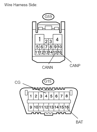
26.CHECK CAN BUS LINES FOR SHORT (MAIN BODY ECU)
a.
U189420E02
2.375,3.854 2.76,4.198 false 1.958,1.885 1.719,2.271 false 2.125,1.875 2.531,2.208 false 1.635,3.302 0.802,2.958 false 0.156,0.083 1.448,0.281 1.292,0.198 10 false Wire Harness Side: 1.583,0.5 1.885,0.656 0.302,0.156 10 false G59 2.469,2.24 2.906,2.385 0.438,0.146 10 false CANP 1.49,2.302 1.927,2.448 0.438,0.146 10 false CANN 1.563,2.792 1.865,2.948 0.302,0.156 10 false G15 2.688,4.24 3.01,4.406 0.323,0.167 10 false BAT 0.521,2.833 0.771,3 0.25,0.167 10 false CG

Disconnect the G59 main body ECU connector.


b.

Measure the resistance of the wire harness side connectors.

Result
Tester Connection Condition Measured Resistance Proceed to
G59-16 (CANP) - G59-15 (CANN) Engine switch off 1 Ω or more OK
G59-16 (CANP) - G59-15 (CANN) Engine switch off Below 1 Ω NG
G59-16 (CANP) - G15-4 (CG) Engine switch off 1 Ω or more OK
G59-15 (CANN) - G15-4 (CG) Engine switch off 1 Ω or more OK
G59-16 (CANP) - G15-4 (CG) Engine switch off Below 1 Ω NG
G59-15 (CANN) - G15-4 (CG) Engine switch off Below 1 Ω NG
G59-16 (CANP) - G15-16 (BAT) Engine switch off 1 Ω or more OK
G59-15 (CANN) - G15-16 (BAT) Engine switch off 1 Ω or more OK
G59-16 (CANP) - G15-16 (BAT) Engine switch off Below 1 Ω NG
G59-15 (CANN) - G15-16 (BAT) Engine switch off Below 1 Ω NG


OK

REPLACE MAIN BODY ECU

NG

REPAIR OR REPLACE CAN MAIN WIRE CONNECTED TO MAIN BODY ECU (NO. 1 JUNCTION CONNECTOR - MAIN BODY ECU)

27.CONNECT CONNECTOR
a.

Reconnect the G81 No. 2 CAN junction connector RH.


NEXT
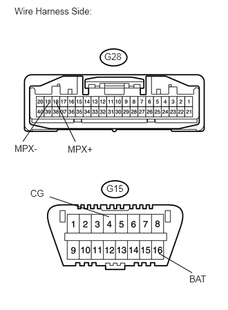
28.CHECK CAN BUS LINES FOR SHORT (NO. 2 JUNCTION CONNECTOR SIDE)
a.
U189421E02
0.844,1.542 1.135,2.135 false 0.74,1.552 0.344,2.135 false 2.396,3.823 2.896,4.115 false 1.646,3.271 0.75,2.969 false 0.219,0.083 1.594,0.281 1.375,0.198 10 false Wire Harness Side: 1.573,0.771 1.865,0.927 0.292,0.156 10 false G28 1.021,2.167 1.438,2.313 0.417,0.146 10 false MPX+ 0.219,2.156 0.635,2.302 0.417,0.146 10 false MPX- 1.604,2.76 1.896,2.917 0.292,0.156 10 false G15 2.854,4.125 3.156,4.292 0.302,0.167 10 false BAT 0.458,2.833 0.708,2.99 0.25,0.156 10 false CG

Disconnect the G82 No. 2 CAN junction connector RH.


b.

Measure the resistance of the wire harness side connectors.

Standard resistance:
Tester Connection Specified Condition
G28-18 (MPX+) - G28-19 (MPX-) 108 to 132 Ω
G28-18 (MPX+) - G15-4 (CG) 200 Ω or more
G28-19 (MPX-) - G15-4 (CG) 200 Ω or more
G28-18 (MPX+) - G15-16 (BAT) 6 kΩ or more
G28-19 (MPX-) - G15-16 (BAT) 6 kΩ or more


NG

29.CHECK CAN BUS LINES FOR SHORT (NO. 2 CAN JUNCTION CONNECTOR RH - NO. 2 JUNCTION CONNECTOR)

OK

37.CONNECT CONNECTOR
29.CHECK CAN BUS LINES FOR SHORT (NO. 2 CAN JUNCTION CONNECTOR RH - NO. 2 JUNCTION CONNECTOR)
a.
U189260E02
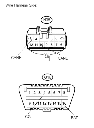
1.531,1.688 2.24,2.021 false 1.156,1.479 0.656,2 false 1.604,3.448 1.021,4.167 false 2.365,3.854 2.698,4.208 false 0.198,0.104 1.583,0.281 1.385,0.177 10 false Wire Harness Side: 1.615,2.74 1.896,2.906 0.281,0.167 10 false G15 1.583,0.635 1.906,0.802 0.323,0.167 10 false N35 0.406,2.021 0.854,2.188 0.448,0.167 10 false CANH 2.115,2.042 2.563,2.208 0.448,0.167 10 false CANL 0.917,4.177 1.177,4.344 0.26,0.167 10 false CG 2.594,4.219 2.906,4.396 0.313,0.177 10 false BAT

Measure the resistance of the wire harness side connectors.

Standard resistance:
Tester Connection Specified Condition
N35-5 (CANH) - N35-10 (CANL) 108 to 132 Ω
N35-5 (CANH) - G15-4 (CG) 200 Ω or more
N35-10 (CANL) - G15-4 (CG) 200 Ω or more
N35-5 (CANH) - G15-16 (BAT) 6 kΩ or more
N35-10 (CANL) - G15-16 (BAT) 6 kΩ or more


OK

30.CONNECT CONNECTOR

NG

REPAIR OR REPLACE CAN MAIN WIRE OR CONNECTOR (NO. 2 CAN JUNCTION CONNECTOR RH - NO. 2 JUNCTION CONNECTOR)

30.CONNECT CONNECTOR
a.

Reconnect the G82 No. 2 CAN junction connector RH.


NEXT

31.CHECK CAN BUS LINES FOR SHORT (NO. 2 JUNCTION CONNECTOR - POWER SLIDE DOOR ECU RH)
NOTICE:

For vehicles without power slide door system, go to "CHECK CAN BUS LINES FOR SHORT (NO. 2 JUNCTION CONNECTOR - COMBINATION METER ECU)"
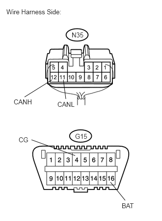

a.
U189261E02
1.104,1.688 0.521,2.052 false 1.344,1.688 1.396,2.094 false 2.344,3.854 2.656,4.24 false 1.594,3.292 0.667,2.958 false 0.135,0.167 1.5,0.344 1.365,0.177 10 false Wire Harness Side: 1.521,0.656 1.813,0.802 0.292,0.146 10 false N35 1.594,2.802 1.885,2.958 0.292,0.156 10 false G15 0.292,2.073 0.719,2.26 0.427,0.188 10 false CANH 1.219,2.125 1.646,2.313 0.427,0.188 10 false CANL 0.396,2.875 0.635,3.042 0.24,0.167 10 false CG 2.583,4.271 2.896,4.438 0.313,0.167 10 false BAT

Disconnect the N35 No. 2 junction connector.


b.

Measure the resistance of the wire harness side connectors.

Result
Tester Connection Condition Measured Resistance Proceed to
N35-12 (CANH) - N35-11 (CANL) Engine switch off 1 Ω or more OK
N35-12 (CANH) - N35-11 (CANL) Engine switch off Below 1 Ω NG
N35-12 (CANH) - G15-4 (CG) Engine switch off 1 Ω or more OK
N35-11 (CANL) - G15-4 (CG) Engine switch off 1 Ω or more OK
N35-12 (CANH) - G15-4 (CG) Engine switch off Below 1 Ω NG
N35-11 (CANL) - G15-4 (CG) Engine switch off Below 1 Ω NG
N35-12 (CANH) - G15-16 (BAT) Engine switch off 1 Ω or more OK
N35-11 (CANL) - G15-16 (BAT) Engine switch off 1 Ω or more OK
N35-12 (CANH) - G15-16 (BAT) Engine switch off Below 1 Ω NG
N35-11 (CANL) - G15-16 (BAT) Engine switch off Below 1 Ω NG


OK

32.CHECK CAN BUS LINES FOR SHORT (NO. 2 JUNCTION CONNECTOR - COMBINATION METER ECU)

NG

33.CONNECT CONNECTOR
32.CHECK CAN BUS LINES FOR SHORT (NO. 2 JUNCTION CONNECTOR - COMBINATION METER ECU)
a.
U189262E02
1.292,1.479 0.854,2.01 false 2.375,3.875 2.688,4.125 false 1.594,3.292 0.719,2.958 false 0.188,0.146 1.552,0.344 1.365,0.198 10 false Wire Harness Side: 1.583,0.688 1.906,0.854 0.323,0.167 10 false N35 1.583,2.781 1.906,2.948 0.323,0.167 10 false G15 0.563,2.042 0.979,2.208 0.417,0.167 10 false CANH 2.177,2.083 2.594,2.25 0.417,0.167 10 false CANL 0.448,2.844 0.677,3.031 0.229,0.188 10 false CG 2.552,4.135 2.865,4.313 0.313,0.177 10 false BAT

Measure the resistance of the wire harness side connectors.

Result
Tester Connection Condition Measured Resistance Proceed to
N35-4 (CANH) - N35-9 (CANL) Engine switch off 1 Ω or more OK
N35-4 (CANH) - N35-9 (CANL) Engine switch off Below 1 Ω NG
N35-4 (CANH) - G15-4 (CG) Engine switch off 1 Ω or more OK
N35-9 (CANL) - G15-4 (CG) Engine switch off 1 Ω or more OK
N35-4 (CANH) - G15-4 (CG) Engine switch off Below 1 Ω NG
N35-9 (CANL) - G15-4 (CG) Engine switch off Below 1 Ω NG
N35-4 (CANH) - G15-16 (BAT) Engine switch off 1 Ω or more OK
N35-9 (CANL) - G15-16 (BAT) Engine switch off 1 Ω or more OK
N35-4 (CANH) - G15-16 (BAT) Engine switch off Below 1 Ω NG
N35-9 (CANL) - G15-16 (BAT) Engine switch off Below 1 Ω NG


NG

REPAIR OR REPLACE NO. 2 JUNCTION CONNECTOR

OK

35.CONNECT CONNECTOR
33.CONNECT CONNECTOR
a.

Reconnect the N35 No. 3 junction connector.


NEXT
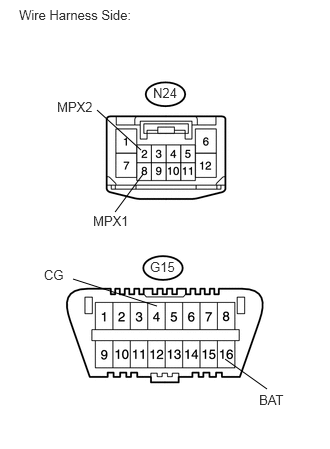
34.CHECK CAN BUS LINES FOR SHORT (POWER SLIDE DOOR ECU RH)
a.
U189422E02
1.49,1.813 1.198,2.208 false 1.469,1.563 1.01,1.146 false 2.344,3.74 2.781,4.052 false 1.635,3.188 0.76,2.906 false 0.198,0.073 1.677,0.271 1.479,0.198 10 false Wire Harness Side: 1.594,0.885 1.885,1.031 0.292,0.146 10 false N24 0.969,2.219 1.375,2.365 0.406,0.146 10 false MPX1 0.594,1.031 1,1.177 0.406,0.146 10 false MPX2 1.563,2.698 1.854,2.844 0.292,0.146 10 false G15 2.698,4.083 3,4.24 0.302,0.156 10 false BAT 0.458,2.781 0.698,2.927 0.24,0.146 10 false CG

Disconnect the N24 power slide door ECU RH connector.


b.

Measure the resistance of the wire harness side connectors.

Result
Tester Connection Condition Measured Resistance Proceed to
N24-8 (MPX1) - N24-2 (MPX2) Engine switch off 1 Ω or more OK
N24-8 (MPX1) - N24-2 (MPX2) Engine switch off Below 1 Ω NG
N24-8 (MPX1) - G15-4 (CG) Engine switch off 1 Ω or more OK
N24-2 (MPX2) - G15-4 (CG) Engine switch off 1 Ω or more OK
N24-8 (MPX1) - G15-4 (CG) Engine switch off Below 1 Ω NG
N24-2 (MPX2) - G15-4 (CG) Engine switch off Below 1 Ω NG
N24-8 (MPX1) - G15-16 (BAT) Engine switch off 1 Ω or more OK
N24-2 (MPX2) - G15-16 (BAT) Engine switch off 1 Ω or more OK
N24-8 (MPX1) - G15-16 (BAT) Engine switch off Below 1 Ω NG
N24-2 (MPX2) - G15-16 (BAT) Engine switch off Below 1 Ω NG


OK

REPLACE POWER SLIDE DOOR ECU RH

NG

REPAIR OR REPLACE CAN BRANCH WIRE CONNECTED TO POWER SLIDE DOOR ECU RH (CANH, CANL)

35.CONNECT CONNECTOR
a.

Reconnect the N27 No. 2 junction connector.


NEXT
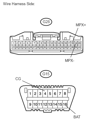
36.CHECK CAN BUS LINES FOR SHORT (COMBINATION METER ECU)
a.
U189016E02
2.656,1.531 2.854,1.021 false 2.771,1.594 2.583,2.094 false 2.406,3.865 2.76,4.156 false 1.635,3.323 0.813,2.948 false 0.115,0.052 1.49,0.25 1.375,0.198 10 false Wire Harness Side: 1.563,0.708 1.865,0.854 0.302,0.146 10 false G28 2.771,0.823 3.198,0.979 0.427,0.156 10 false MPX+ 2.375,2.125 2.771,2.281 0.396,0.156 10 false MPX- 2.688,4.188 2.979,4.344 0.292,0.156 10 false BAT 0.563,2.792 0.813,2.927 0.25,0.135 10 false CG 1.552,2.615 1.854,2.76 0.302,0.146 10 false G15

Disconnect the G28 combination meter ECU connector.


b.

Measure the resistance of the wire harness side connectors.

Result
Tester Connection Condition Measured Resistance Proceed to
G28-18 (MPX+) - G28-19 (MPX-) Engine switch off 1 Ω or more OK
G28-18 (MPX+) - G28-19 (MPX-) Engine switch off Below 1 Ω NG
G28-18 (MPX+) - G15-4 (CG) Engine switch off 1 Ω or more OK
G28-19 (MPX-) - G15-4 (CG) Engine switch off 1 Ω or more OK
G28-18 (MPX+) - G15-4 (CG) Engine switch off Below 1 Ω NG
G28-19 (MPX-) - G15-4 (CG) Engine switch off Below 1 Ω NG
G28-18 (MPX+) - G15-16 (BAT) Engine switch off 1 Ω or more OK
G28-19 (MPX-) - G15-16 (BAT) Engine switch off 1 Ω or more OK
G28-18 (MPX+) - G15-16 (BAT) Engine switch off Below 1 Ω NG
G28-19 (MPX-) - G15-16 (BAT) Engine switch off Below 1 Ω NG


OK

REPLACE COMBINATION METER ASSEMBLY (COMBINATION METER ECU)

NG

REPAIR OR REPLACE CAN MAIN WIRE CONNECTED TO COMBINATION METER ASSEMBLY (COMBINATION METER ECU - NO. 2 JUNCTION CONNECTOR)

37.CONNECT CONNECTOR
a.

Reconnect the G82 No. 2 CAN junction connector RH.


NEXT
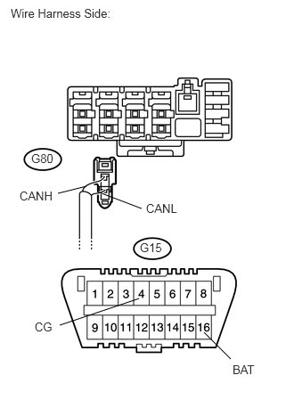
38.CHECK CAN BUS LINES FOR SHORT (NO. 2 CAN JUNCTION CONNECTOR RH - CERTIFICATION ECU)
a.
U189391E02
1.01,2.177 0.677,2.26 false 1.135,2.24 1.656,2.438 false 2.385,3.885 2.698,4.198 false 1.625,3.49 0.698,3.802 false 0.125,0.073 1.49,0.25 1.365,0.177 10 false Wire Harness Side: 0.365,1.771 0.656,1.938 0.292,0.167 10 false G80 0.229,2.208 0.656,2.365 0.427,0.156 10 false CANH 1.708,2.354 2.135,2.51 0.427,0.156 10 false CANL 1.635,2.813 1.927,2.958 0.292,0.146 10 false G15 2.719,4.24 3.021,4.396 0.302,0.156 10 false BAT 0.406,3.74 0.656,3.896 0.25,0.156 10 false CG

Disconnect the G80 No. 2 CAN junction connector RH.


b.

Measure the resistance of the wire harness side connectors.

Result
Tester Connection Condition Measured Resistance Proceed to
G80-1 (CANH) - G80-2 (CANL) Engine switch off 1 Ω or more OK
G80-1 (CANH) - G80-2 (CANL) Engine switch off Below 1 Ω NG
G80-1 (CANH) - G15-4 (CG) Engine switch off 1 Ω or more OK
G80-2 (CANL) - G15-4 (CG) Engine switch off 1 Ω or more OK
G80-1 (CANH) - G15-4 (CG) Engine switch off Below 1 Ω NG
G80-2 (CANL) - G15-4 (CG) Engine switch off Below 1 Ω NG
G80-1 (CANH) - G15-16 (BAT) Engine switch off 1 Ω or more OK
G80-2 (CANL) - G15-16 (BAT) Engine switch off 1 Ω or more OK
G80-1 (CANH) - G15-16 (BAT) Engine switch off Below 1 Ω NG
G80-2 (CANL) - G15-16 (BAT) Engine switch off Below 1 Ω NG


NG

39.CONNECT CONNECTOR

OK

REPAIR OR REPLACE NO. 2 JUNCTION CONNECTOR RH

39.CONNECT CONNECTOR
a.

Reconnect the G80 No. 2 CAN junction connector RH.


NEXT
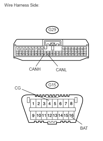
40.CHECK CAN BUS LINES FOR SHORT (CERTIFICATION ECU)
a.
U189409E02
1.49,1.781 1.198,2.198 false 1.583,1.792 1.927,2.198 false 1.635,3.333 0.729,2.958 false 2.385,3.885 2.74,4.125 false 1.615,0.896 1.896,1.052 0.281,0.156 10 false G29 1.615,2.729 1.896,2.885 0.281,0.156 10 false G15 0.969,2.208 1.406,2.344 0.438,0.135 10 false CANH 1.865,2.229 2.344,2.427 0.479,0.198 10 false CANL 0.49,2.833 0.729,2.969 0.24,0.135 10 false CG 2.677,4.167 3.01,4.344 0.333,0.177 10 false BAT 0.146,0.083 1.521,0.281 1.375,0.198 10 false Wire Harness Side:

Disconnect the G29 certification ECU connector.


b.

Measure the resistance of the wire harness side connectors.

Result
Tester Connection Condition Measured Resistance Proceed to
G29-27 (CANH) - G29-28 (CANL) Engine switch off 1 Ω or more OK
G29-27 (CANH) - G29-28 (CANL) Engine switch off Below 1 Ω NG
G29-27 (CANH) - G15-4 (CG) Engine switch off 1 Ω or more OK
G29-28 (CANL) - G15-4 (CG) Engine switch off 1 Ω or more OK
G29-27 (CANH) - G15-4 (CG) Engine switch off Below 1 Ω NG
G29-28 (CANL) - G15-4 (CG) Engine switch off Below 1 Ω NG
G29-27 (CANH) - G15-16 (BAT) Engine switch off 1 Ω or more OK
G29-28 (CANL) - G15-16 (BAT) Engine switch off 1 Ω or more OK
G29-27 (CANH) - G15-16 (BAT) Engine switch off Below 1 Ω NG
G29-28 (CANL) - G15-16 (BAT) Engine switch off Below 1 Ω NG


OK

REPLACE CERTIFICATION ECU

NG

REPAIR OR REPLACE CAN BRANCH WIRE CONNECTED TO CERTIFICATION ECU (CANH, CANL)

41.CHECK CAN BUS LINE FOR DISCONNECTION
a.

Recheck for DTC.


NEXT

GO TO DTC CHART