2011-2016 FJ Cruiser · Service Manual RESTRAINTS

INSTALLATION

Removal / installation · Vehicles built Jul 2007 – Oct 2010

Versions by build date: Jul 2007 – Oct 2010 Nov 2010 – Jul 2012 from Aug 2012

HINT:
The procedure described below is for the LH side. Use the same procedure for both the LH and RH sides, unless otherwise specified.


1. PRECAUTION

CAUTION:
Read "PRECAUTION" thoroughly before servicing (Click here).


2. INSTALL REAR AIRBAG SENSOR LH
  1. Check that the ignition switch is turned to OFF.

  1. Check that the battery negative (-) terminal is disconnected.

    CAUTION:
    After disconnecting the negative battery terminal, wait for at least 90 seconds before starting the operation.

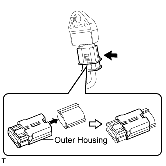
  1. C128268E01
    Connect the connector to the rear airbag sensor LH.

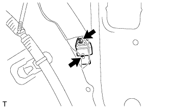
  1. C128266
    Install the rear airbag sensor LH with the nut.

    Torque:
    9.0 N*m{ 92 kgf*cm , 80 in.*lbf }

    CAUTION:
    1. If the rear airbag sensor LH has been dropped, or there are any cracks, dents or other defects in the case or connector, replace it with a new one.
    2. When installing the rear airbag sensor LH, make sure that the SRS wiring does not interfere with any other parts and that it is not pinched between other parts.

  1. Check that there is no looseness in the installation parts of the rear airbag sensor LH.


3. INSTALL DECK TRIM SIDE PANEL ASSEMBLY RH (for RH Side)

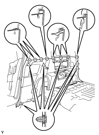
  1. B130617
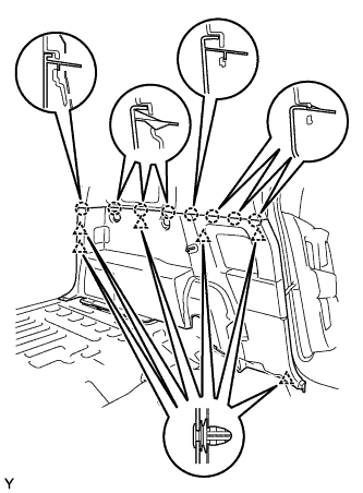
    Engage the 6 clips and the 8 claws and install the deck trim side panel.

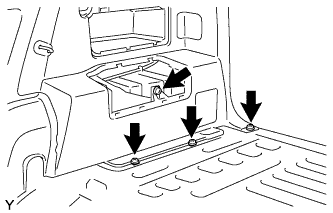
  1. B130616
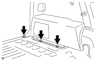
    Tighten the 3 screws.

  1. Tighten the bolt.

    Torque:
    5.5 N*m{ 56 kgf*cm , 49 in.*lbf }


4. INSTALL DECK TRIM SIDE PANEL ASSEMBLY LH

  1. B130619
    Engage the 6 clips and the 8 claws and install the deck trim side panel.

  1. B130618
    Tighten the 3 screws.


5. INSTALL REAR SEAT OUTER BELT ASSEMBLY LH

  1. B130782E01
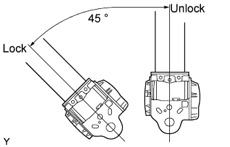
    Check the angle of inclination required to lock the retractor.

    1. Gently incline the retractor from its initial position. Check that the belt does not lock when the retractor is inclined 15° or less in any direction. Also, check that the belt locks when the inclination of the retractor is 45° or more.

      NOTICE:
      Do not disassemble the retractor.

      If the operation is not as specified, replace the rear seat outer belt.

  1. B130780E01
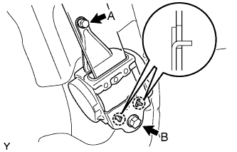
    Hook the lower stay of the retractor onto the 2 body hooks and provisionally install the retractor with the 2 bolts.

  1. Tighten bolt A and then bolt B.

    Torque:
    8.5 N*m{ 87 kgf*cm , 75 in.*lbf } for bolt A
    42 N*m{ 428 kgf*cm , 31 ft.*lbf } for bolt B

  1. B130781
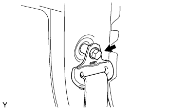
    Install the through anchor with the bolt.

    Torque:
    42 N*m{ 428 kgf*cm , 31 ft.*lbf }

  1. Make sure that the shoulder anchor rotates smoothly.

  1. Check that the ELR locks.

    NOTICE:
    Perform the check with the front seat outer belt installed.


    1. With the belt installed, check that the belt locks when it is pulled out quickly.
      If the operation is not as specified, replace the rear seat outer belt.


6. INSTALL LAP BELT OUTER ANCHOR COVER

  1. B138385
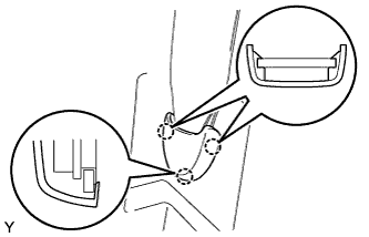
    Engage the 3 claws and install the lap belt outer anchor cover.


7. INSTALL QUARTER TRIM POCKET (w/o Woofer) (for RH Side)

  1. B130613
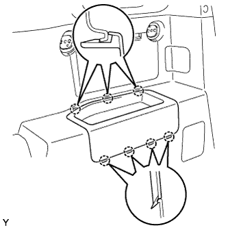
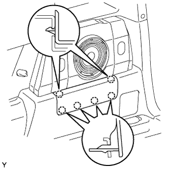
    Engage the 6 claws and install the quarter trim pocket.


8. INSTALL SIDE TRIM COVER (w/o Woofer) (for RH Side)

  1. B130612
    Engage the 8 claws and install the side trim cover.


9. INSTALL QUARTER TRIM POCKET TRAY (w/o Woofer) (for RH Side)

  1. B130611
    Engage the 7 claws and install the quarter trim pocket tray.


10. INSTALL PACKAGE HOLDER NET HOOK

B130610E02

HINT:
Use the same procedure to install all the package holder net hooks.

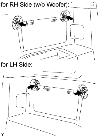
  1. Install the package holder net hook with the bolt.

    Torque:
    8.1 N*m{ 83 kgf*cm , 72 in.*lbf }


11. INSTALL AMPLIFIER BOX SPEAKER ASSEMBLY (w/ Woofer)

  1. B134990
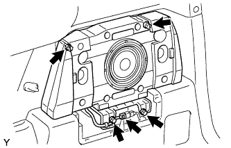
    Install the amplifier box speaker with the 4 screws.

    Torque:
    8.1 N*m{ 85 kgf*cm , 72 in.*lbf }

  1. Connect the speaker connector.


12. INSTALL SPEAKER MOUNTING COVER (w/ Woofer)

  1. B134991
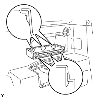
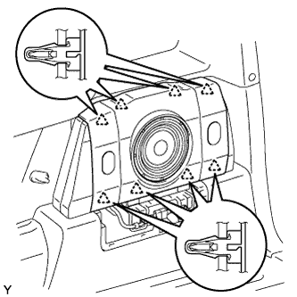
    Engage the 8 clips and install the speaker mounting cover.


13. INSTALL DECK SIDE GARNISH (w/ Woofer)

  1. B134992
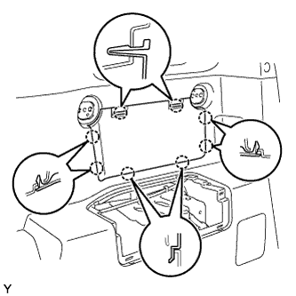
    Engage the 6 claws and install the deck side garnish.


14. INSTALL FRONT DOOR OPENING TRIM WEATHERSTRIP LH

  1. B130604E01
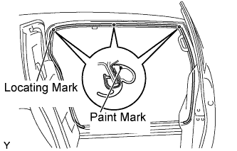
    Align the locating marks with the paint marks first, and install the front door opening trim weatherstrip, as shown in the illustration.

    Paint mark:
    Area
    Color
    RH side
    White
    LH side
    Red


15. INSTALL ACCESS DOOR SCUFF PLATE LH

  1. B130598
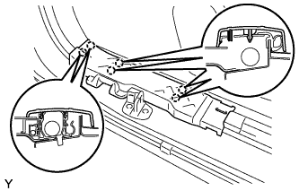
    Engage the 6 claws and install the access door scuff plate.


16. INSTALL FRONT DOOR SCUFF PLATE LH

  1. B130597
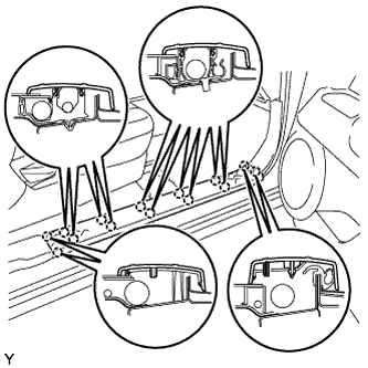
    Engage the 14 claws and install the door scuff plate.


17. INSTALL REAR FLOOR MAT ASSEMBLY

  1. B130594
    Install the rear floor mat with the 2 clips.


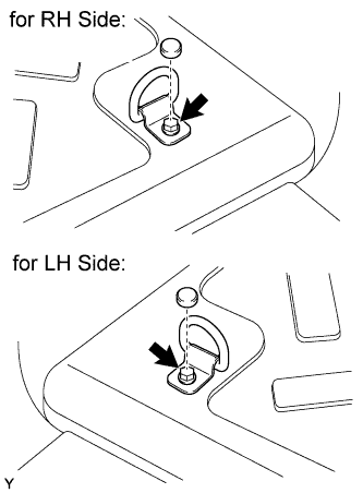
18. INSTALL LUGGAGE HOLD BELT STRIKER ASSEMBLY

B179163E01

HINT:
Use the same procedure for both sides.

  1. Install the luggage hold belt striker with the bolt.

    Torque:
    18 N*m{ 184 kgf*cm , 13 ft.*lbf }

  1. Install the cap.


19. INSTALL REAR FLOOR MAT SUPPORT PLATE

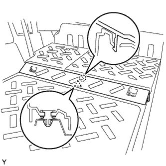
  1. B130593
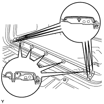
    Engage the 11 claws and install the rear floor mat support plate.

  1. B130592
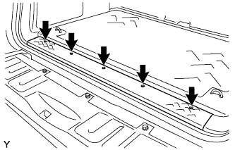
    Tighten the 5 screws.


20. INSTALL REAR FLOOR BOARD

  1. B135075
    Engage the clip and claw and install the rear floor board.

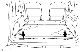
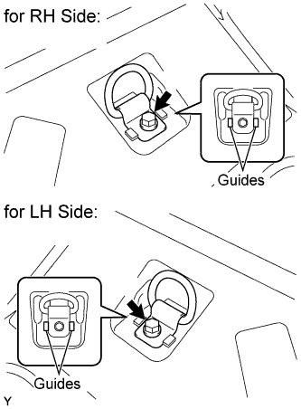
  1. B135074E02
    Install the luggage hold belt striker with the bolt.

    Torque:
    18 N*m{ 184 kgf*cm , 13 ft.*lbf }

    HINT:
    Use the same procedure for both sides.


21. INSTALL REAR SEATBACK ASSEMBLY LH

  1. B130721E01
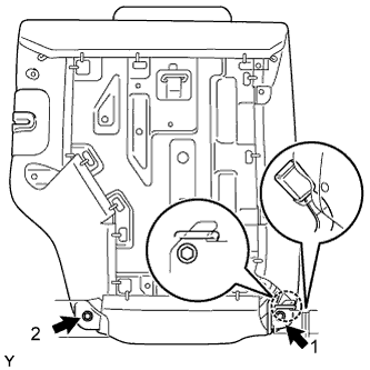
    Engage the hook and temporarily install the rear seatback with the 2 bolts.

  1. Tighten the 2 bolts in the sequence shown in the illustration.

    Torque:
    37 N*m{ 375 kgf*cm , 27 ft.*lbf }

  1. Install the rear center seat inner belt into the rear seatback holder.


22. INSTALL REAR SEATBACK BOARD CARPET ASSEMBLY LH

  1. B130720
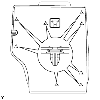
    Engage the 8 clips and install the rear seatback board carpet.

  1. Pull up the rear seatback.


23. CONNECT CABLE TO NEGATIVE BATTERY TERMINAL

Torque:
3.9 N*m{ 40 kgf*cm , 35 in.*lbf }


24. PERFORM INITIALIZATION
  1. Perform initialization (Click here).

    HINT:
    Some systems need initialization when disconnecting the cable from the negative battery terminal.


25. INSPECT SRS WARNING LIGHT
  1. Inspect the SRS warning light (Click here).

← REMOVAL (from Aug 2012)INSTALLATION (Nov 2010 – Jul 2012) →