Home › RESTRAINTS › SUPPLEMENTAL RESTRAINT SYSTEM › REAR AIRBAG SENSORREMOVAL
Removal / installation · Vehicles built Nov 2010 – Jul 2012
Versions by build date: Jul 2007 – Oct 2010 Nov 2010 – Jul 2012 from Aug 2012
HINT:
The procedure described below is for the LH side. Use the same procedure for both the RH and LH sides, unless otherwise specified.
1.
PRECAUTION
CAUTION:
Some of these service operations affect the SRS airbag system. Read the precautionary notices concerning the SRS airbag system before servicing (Click here ).
2.
DISCONNECT CABLE FROM NEGATIVE BATTERY TERMINAL
CAUTION:
Wait at least 90 seconds after disconnecting the cable from the negative (-) battery terminal to disable the SRS system.
3.
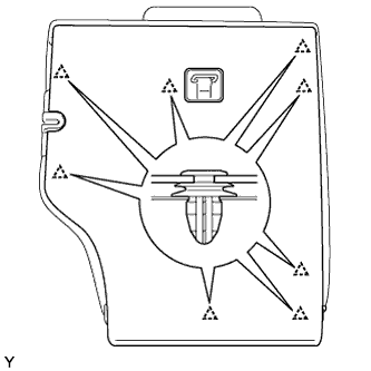
REMOVE REAR SEATBACK BOARD CARPET ASSEMBLY LH (for LH Side)
Pull the rear seatback lock release button and tilt the rear seatback forward. Disengage the 8 clips and remove the rear seatback board carpet.
4.
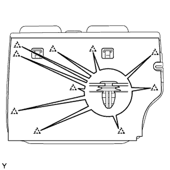
REMOVE REAR SEATBACK BOARD CARPET ASSEMBLY RH (for RH Side)
Pull the rear seatback lock release button and tilt the rear seatback forward. Disengage the 10 clips and remove the rear seatback board carpet.
5.
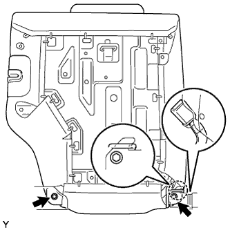
REMOVE REAR SEATBACK ASSEMBLY LH (for LH Side)
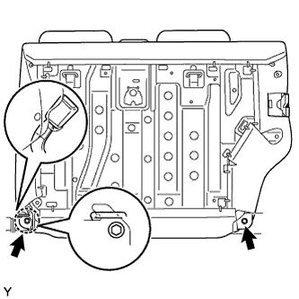
Remove the rear center seat inner belt from the rear seatback holder. Remove the 2 bolts.
Disengage the hook and remove the rear seatback.
6.
REMOVE REAR SEATBACK ASSEMBLY RH (for RH Side)
Pull up the rear seatback. Remove the bolt and the anchor plate of the rear center seat outer belt.
Remove the rear seat inner belt from the rear seatback holder. Pull the rear seatback lock release button and tilt the rear seatback forward.
Remove the 2 bolts.
Disengage the hook and remove the rear seatback.
7.
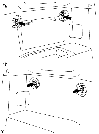
REMOVE REAR FLOOR BOARD
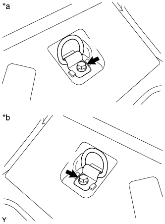
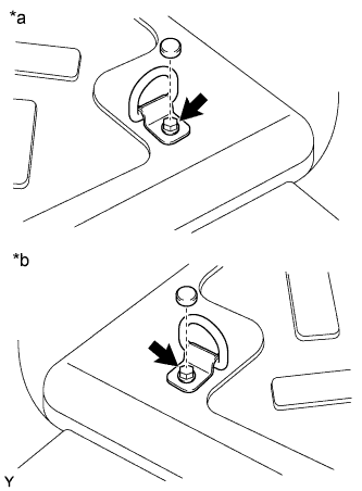
Remove the bolt and the luggage hold belt striker.
Text in Illustration
*a
for RH Side
*b
for LH Side
HINT:
Use the same procedure for both sides.
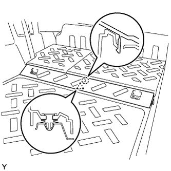
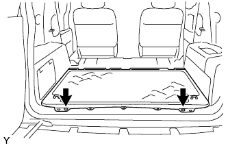
Disengage the clip and the claw and remove the rear floor board.
8.
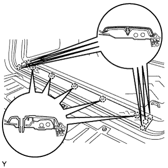
REMOVE REAR FLOOR MAT SUPPORT PLATE
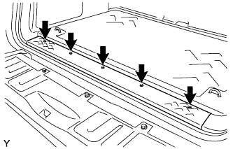
Remove the 5 screws.
Disengage the 11 claws and remove the rear floor mat support plate.
9.
REMOVE LUGGAGE HOLD BELT STRIKER ASSEMBLY
HINT:
Use the same procedure for both sides.
Remove the cap.
Text in Illustration
*a
for RH Side
*b
for LH Side
Remove the bolt and the luggage hold belt striker.
10.
REMOVE REAR FLOOR MAT ASSEMBLY
Using a clip remover, remove the 2 clips and the rear floor mat.
11.
REMOVE FRONT DOOR SCUFF PLATE
Disengage the 14 claws and remove the front door scuff plate.
12.
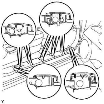
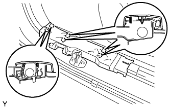
REMOVE ACCESS DOOR SCUFF PLATE
Disengage the 6 claws and remove the access door scuff plate.
13.
REMOVE FRONT DOOR OPENING TRIM WEATHERSTRIP
Remove the front door opening trim weatherstrip to the extent that the deck trim side panel removed.
14.
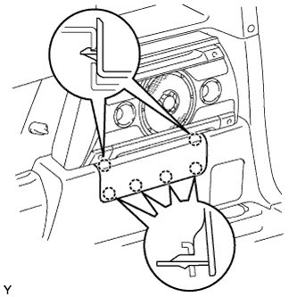
REMOVE DECK SIDE GARNISH (w/ Woofer)
Disengage the 6 claws and remove the rear deck side garnish.
15.
REMOVE SPEAKER MOUNTING COVER (w/ Woofer)
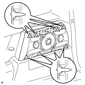
Disengage the 8 clips and 2 guides and remove the speaker mounting cover.
16.
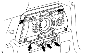
REMOVE AMPLIFIER BOX SPEAKER ASSEMBLY (w/ Woofer)
Disconnect the connectors. Remove the 4 screws and the amplifier box speaker.
17.
REMOVE PACKAGE HOLDER NET HOOK (w/o Woofer)
HINT:
Use the same procedure to remove all the package holder net hooks.
Text in Illustration
*a
for RH Side without Woofer
*b
for LH Side
Remove the screw and the package holder net hook.
18.
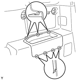
REMOVE QUARTER TRIM POCKET TRAY (w/o Woofer)
Disengage the 7 claws and remove the quarter trim pocket tray.
19.
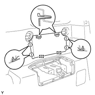
REMOVE SIDE TRIM COVER (w/o Woofer)
Disengage the 6 claws and the 2 guides and remove the side trim cover.
20.
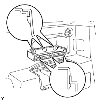
REMOVE QUARTER TRIM POCKET (w/o Woofer)
Disengage the 6 claws and remove the quarter trim pocket.
21.
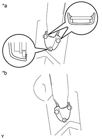
REMOVE LAP BELT OUTER ANCHOR COVER
HINT:
Use the same procedure for both sides.
Text in Illustration
*a
for RH Side
*b
for LH Side
Disengage the 3 claws and remove the lap belt outer anchor cover.
22.
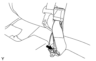
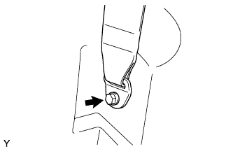
SEPARATE REAR SEAT OUTER BELT ASSEMBLY
Remove the bolt and the anchor plate.
23.
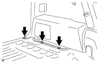
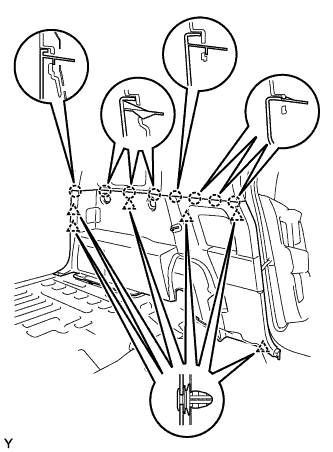
REMOVE DECK TRIM SIDE PANEL ASSEMBLY LH (for LH Side)
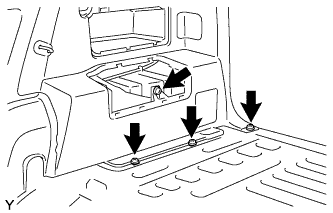
Remove the 3 screws.
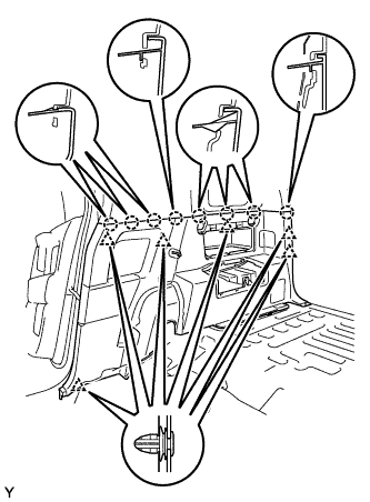
Disengage the 6 clips and the 8 claws and remove the deck trim side panel.
24.
REMOVE DECK TRIM SIDE PANEL ASSEMBLY RH (for RH Side)
Remove the 3 screws and the bolt.
Disengage the 6 clips and the 8 claws and remove the deck trim side panel.
25.
REMOVE REAR AIRBAG SENSOR
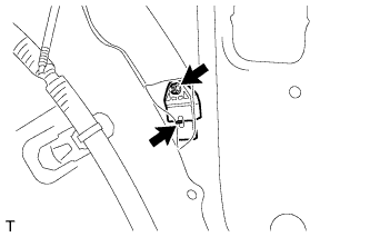
Remove the nut and the rear airbag sensor.
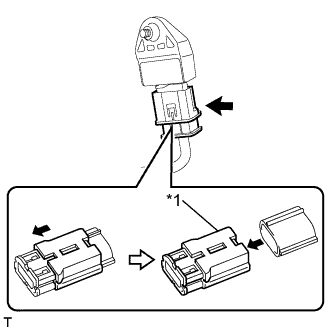
Disconnect the connector from the rear airbag sensor.
Text in Illustration
*1
Outer Housing