REMOVAL
Removal / installation · Vehicles built from Jul 2007
| 1.
DISCONNECT CABLE FROM NEGATIVE BATTERY TERMINAL |
|
| 3.
REMOVE NO.1 ENGINE UNDER COVER SUB-ASSEMBLY |
|
| 4.
REMOVE REAR ENGINE UNDER COVER ASSEMBLY |
|
| 5.
DRAIN DIFFERENTIAL OIL |
|
| 6.
REMOVE FRONT PROPELLER SHAFT ASSEMBLY
|
 |
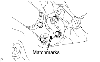
Place matchmarks on the propeller shaft flange and differential flange.
Remove the 4 nuts, 4bolts and 4 washers.
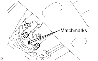
- Place matchmarks on the propeller shaft flange and transfer flange.
Remove the 4 nuts, 4 washers and the propeller shaft assembly.
| 7.
SEPARATE SPEED SENSOR FRONT LH
|
|
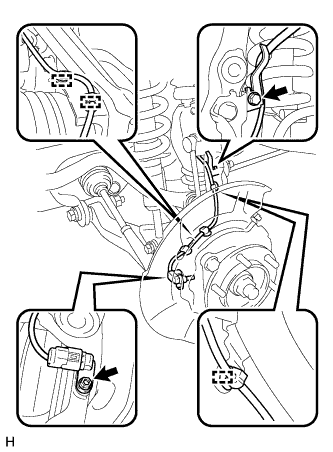
Type A:
- Using a 5 mm hexagon wrench, remove the bolt and separate the front speed sensor.
Disengage the 3 clamps.
Remove the bolt and separate the skid control sensor wire from the steering knuckle.
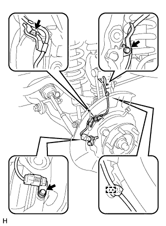
Type B:
- Remove the bolt and separate the front speed sensor.
Disengage the clamp.
Remove the 2 bolts and separate the skid control sensor wire from the steering knuckle.
| 8.
SEPARATE FRONT SPEED SENSOR RH |
|
- HINT:
- Use the same procedure as for the RH side.
| 9.
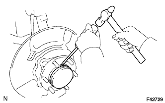
REMOVE FRONT AXLE HUB GREASE CAP LH
|
|
Using a screwdriver and a hammer, remove the front axle hub grease cap.
- NOTICE:
- Do not damage the axle hub.
| 10.
REMOVE FRONT AXLE HUB GREASE CAP RH |
|
- HINT:
- Use the same procedure as for the RH side.
| 11.
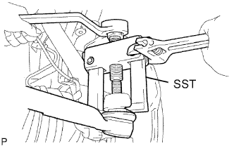
SEPARATE TIE ROD END SUB-ASSEMBLY LH
|
|
Remove the cotter pin and nut.
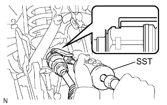
- Using SST, separate the tie rod end from the steering knuckle.
- SST
- 09628-62011
| 12.
SEPARATE TIE ROD END SUB-ASSEMBLY RH |
|
| 13.
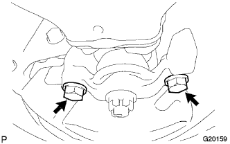
SEPARATE FRONT LOWER BALL JOINT ATTACHMENT
|
|
Remove the 2 bolts and separate the front lower ball joint attachment from the steering knuckle.
| 14.
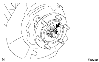
REMOVE FRONT AXLE HUB NUT LH
|
|
Remove the cotter pin and adjusting lock cap.
Remove the front axle hub nut.
| 15.
REMOVE FRONT AXLE HUB NUT RH |
|
- HINT:
- Use the same procedure as for the RH side.
| 16.
REMOVE FRONT DRIVE SHAFT ASSEMBLY LH
|
|
Using SST, remove the front drive shaft.
- SST
- 09520-01010
09520-24010
(09520-32040)
- NOTICE:
- Do not damage the oil seal.
| 17.
REMOVE FRONT DRIVE SHAFT ASSEMBLY RH |
|
- HINT:
- Use the same procedure as for the RH side.
| 18.
REMOVE FRONT DIFFERENTIAL CARRIER ASSEMBLY |
|
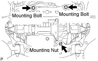
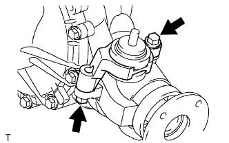
Remove the bolt and disconnect the differential breather tube bracket.
Support the differential with a jack.
Remove the No. 1 differential mounting nut.
Remove the 2 mounting bolts and 2 nuts.
Lower the jack and remove the front differential.
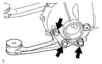
- Remove the 3 bolts and front No. 1 differential support.
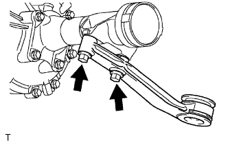
- Remove the 2 bolts and front No. 2 differential support.
- Remove the 2 bolts and front No. 3 differential support.