REMOVAL
Removal / installation · Vehicles built Jul 2007 – Jul 2009
Versions by build date: Jul 2007 – Jul 2009 from Aug 2009
| 1.
DISCONNECT CABLE FROM NEGATIVE BATTERY TERMINAL |
|
| 3.
DRAIN BRAKE FLUID |
 |
- HINT:
- Immediately wash off any brake fluid that comes into contact with any painted surfaces.
| 4.
DRAIN DIFFERENTIAL OIL |
|
| 5.
REMOVE REAR DISC BRAKE CALIPER ASSEMBLY LH
|
|
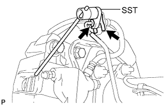
Using SST, separate the brake tube.
- SST
- 09023-00101
- HINT:
- Use a container to catch the brake fluid.
Remove the clip and flexible hose.
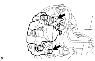
- Remove the 2 bolts and 2 washers and remove the disc brake caliper assembly.
| 6.
REMOVE REAR DISC BRAKE CALIPER ASSEMBLY RH |
|
- HINT:
- Use the same procedure as for the LH side.
| 7.
REMOVE REAR DISC
|
|
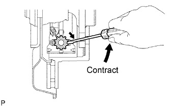
Release the parking brake lever.
- Place matchmarks on the disc and axle hub and remove the disc.
- HINT:
- If the disc cannot be removed easily, turn the shoe adjuster until the wheel turns freely.
| 8.
REMOVE PARKING BRAKE SHOE RETURN TENSION SPRING
|
|
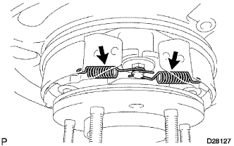
Using needle-nose pliers, remove the 2 return tension springs.
| 9.
REMOVE PARKING BRAKE SHOE STRUT LH
|
|
Remove the parking brake shoe strut and compression spring.
| 10.
REMOVE PARKING BRAKE SHOE
|
|
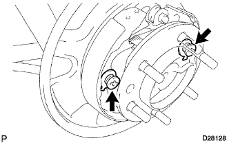
Remove the 2 hold down spring cups, hold down compression spring and hold down spring pin.
Disconnect the return tension spring and remove the No. 2 shoe.
Remove the shoe adjusting screw set and return tension spring.
Remove the 2 hold down spring cups, hold down compression spring and hold down spring pin.
Using needle-nose pliers, disconnect the parking brake cable and remove the No. 1 shoe.
| 11.
SEPARATE PARKING BRAKE CABLE LH
|
|
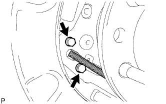
Remove the 2 bolts and separate the parking brake cable from the parking brake plate.
| 12.
REMOVE PARKING BRAKE CABLE RH |
|
- HINT:
- Use the same procedure as for the LH side.
| 13.
REMOVE REAR SPEED SENSOR
|
|
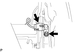
Disconnect the skid control sensor wire.
Remove the nut and rear speed sensor.
- NOTICE:
- Do not attach any foreign matter to the sensor tip.
- Ensure that no foreign matter enters the sensor installation part.
| 14.
REMOVE REAR SPEED SENSOR RH |
|
- HINT:
- Use the same procedure as for the LH side.
| 15.
REMOVE REAR AXLE SHAFT RH
|
|
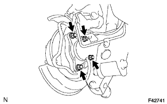
Remove the 4 nuts and rear axle shaft with parking brake plate.
Remove the O-ring.
| 16.
REMOVE REAR AXLE SHAFT LH |
|
- HINT:
- Use the same procedure as for the LH side.
| 17.
REMOVE REAR AXLE SHAFT LH OIL SEAL
|
|
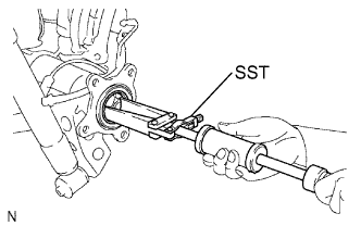
Using SST, remove the oil seal.
- SST
- 09308-00010
| 18.
REMOVE REAR AXLE SHAFT RH OIL SEAL |
|
- HINT:
- Use the same procedure as for the LH side.
| 19.
REMOVE REAR PROPELLER SHAFT ASSEMBLY
|
|
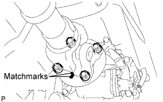
Place matchmarks on the propeller shaft flange and transfer flange.
Remove the 4 nuts and 4 washers.
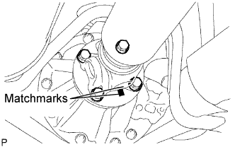
- Place matchmarks on the propeller shaft flange and differential flange.
Remove the 4 nuts, 4 bolts, 4 washers and the propeller shaft assembly.
| 20.
REMOVE REAR DIFFERENTIAL CARRIER ASSEMBLY |
|
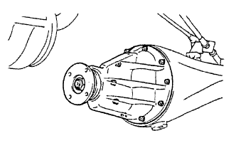
Remove the 10 nuts and the differential carrier.
- NOTICE:
- Be careful not to damage the contact surface.
| 21.
REMOVE REAR DIFFERENTIAL CARRIER GASKET |
|