TERMINALS OF ECU
System information · Vehicles built Jul 2007 – Oct 2010
Versions by build date: Jul 2007 – Oct 2010 from Nov 2010
| CLEARANCE WARNING ECU (w/o Rear Fog Light) |


Disconnect the E31 clearance warning ECU connector.
Measure the voltage according to the value(s) in the table below.
Standard Voltage Terminal No. (Symbol)
Wiring Color
Terminal Description
Condition
Specified Condition
E31-3 (+B) - Body ground
LG - Body ground
Clearance sonar main switch signal
Ignition switch ON, back sonar switch ON
9 to 15 V
Ignition switch ON, back sonar switch OFF
Below 1.5 V
E31-10 (E) - Body ground
W-B - Body ground
Body ground
Always
Below 1 V
- HINT:
- If the result is not as specified, there may be a malfunction on the wire harness side.
Reconnect the clearance warning ECU connector.
Measure the voltage according to the vale(s) in the table below.
Standard Voltage Terminal No. (Symbol)
Wiring Color
Terminal Description
Condition
Specified Condition
E31-2 (BBZ) - E31-10 (E)
L-B - W-B
Buzzer input
Ignition switch ON, back sonar switch ON
Pulse generation
(See waveform 1)
Ignition switch ON, back sonar switch OFF
Below 1 V
E31-12 (S6) - E31-11 (E1)
P - Y
No. 1 ultrasonic sensor (LH)
When signal transmitted from ECU to No. 1 ultrasonic sensor (LH)
Pulse generation
(See waveform 2)
E31-6 (S5) - E31-5 (E2)
B - W
No. 1 ultrasonic sensor (RH)
When signal transmitted from ECU to No. 1 ultrasonic sensor (RH)
E31-8 (RL) - Body ground
R-Y - Body ground
Back-up light switch signal input
Ignition switch ON, shift lever in R
11 to 14 V
Ignition switch ON, shift lever not in R
Below 1 V
- HINT:
- If the result is not as specified, the clearance warning ECU may have a malfunction.
Using an oscilloscope, check waveform 1.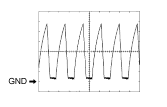
Waveform 1Terminal Connection
E31-2 (BBZ) - E31-10 (E)
Tester Range
2 V/DIV., 200 μsec./DIV.
Vehicle Condition
When sonar detects obstacle (buzzer sounds)
Using an oscilloscope, check waveform 2.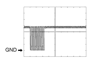
Waveform 2Terminal Connection
E31-6 (S5) - E31-5 (E2)
E31-12 (S6) - E31-11 (E1)
Tester Range
2 V/DIV., 200 μsec./DIV.
Vehicle Condition
Ignition switch ON, back sonar switch ON
| CLEARANCE WARNING ECU (w/ Rear Fog Light) |

Disconnect the E76 clearance warning ECU connector.
Measure the voltage or resistance according to the value(s) in the table below.
Standard Terminal No. (Symbol)
Wiring Color
Terminal Description
Condition
Specified Condition
E76-10 (IG) - Body ground
LG - Body ground
Clearance sonar main switch signal
Ignition switch ON, back sonar switch ON
9 to 15 V
Ignition switch ON, back sonar switch OFF
Below 1.5 V
E76-21 (E) - Body ground
W-B - Body ground
Body ground
Always
Below 1 Ω
E76-21 (E) - E76-22 (E2)
W-B - W
Ground for ultrasonic sensor
Always
Below 1 Ω
- HINT:
- If the result is not as specified, there may be a malfunction on the wire harness side.
Reconnect the clearance warning ECU connector.
Measure the voltage according to the vale(s) in the table below.
Standard Voltage Terminal No. (Symbol)
Wiring Color
Terminal Description
Condition
Specified Condition
E76-3 (SPD) - E76-21 (E)
V-R - W-B
Vehicle speed signal
Ignition switch ON, turn drive wheels slowly
Pulse generation
E76-6 (SOR) - E76-21 (E)
B - W-B
Rear sensor communication signal
Ignition switch ON, back sonar switch ON
Pulse generation
(See waveform 1)
E76-12 (BBZ) - E76-21 (E)
L-B - W-B
Clearance warning buzzer signal
Buzzer sounding
Pulse generation
(See waveform 2)
E76-13 (RL) - E76-21 (E)
R-Y - W-B
Reverse position signal
Ignition switch ON, shift lever not in R
Below 1.5 V
Ignition switch ON, shift lever in R
7 V or higher
E76-24 (BOR) - E76-21 (E)
R-L - W-B
Power source for rear sensor circuit
Ignition switch off
Below 1.5 V
Ignition switch ON
7.2 to 8.8 V
- HINT:
- If the result is not as specified, the clearance warning ECU may have a malfunction.
Using an oscilloscope, check waveform 1.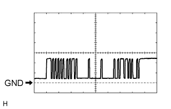
Waveform 1Terminal Connection
E76-6 (SOR) - E76-21 (E)
Tester Range
2 V/DIV., 200 μsec./DIV.
Vehicle Condition
Ignition switch ON, back sonar switch ON
Using an oscilloscope, check waveform 2.
Waveform 2Terminal Connection
E76-12 (BBZ) - E76-21 (E)
Tester Range
2 V/DIV., 200 μsec./DIV.
Vehicle Condition
When sonar detects obstacle (buzzer sounds)