2011-2016 FJ Cruiser · Service Manual BODY ELECTRICAL

Back Sonar Sensor LH Circuit

Circuit diagnosis · Vehicles built from Nov 2010

Versions by build date: Jul 2007 – Oct 2010 from Nov 2010

CAUTION / NOTICE / HINT

HINT:
This procedure applies only for vehicles without rear fog lights.


DESCRIPTION

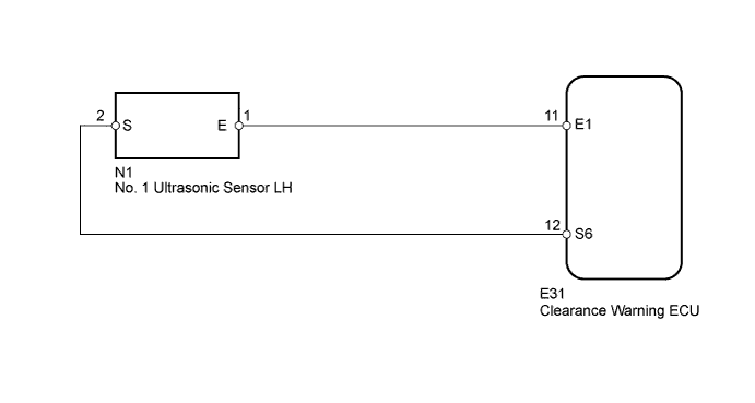
An ultrasonic sensor consists of a sensor portion that transmits and receives ultrasonic waves and a pre-amplifier that amplifies them. The ultrasonic sensor outputs the ultrasonic waves and sends the received signals to the clearance warning ECU.

WIRING DIAGRAM

E148134E03

INSPECTION PROCEDURE


1. INSPECT NO. 1 ULTRASONIC SENSOR LH

  1. E160757E01
    Remove the No. 1 ultrasonic sensor LH.

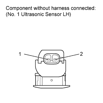
  1. Measure the resistance according to the value(s) in the table below.
    Standard Resistance:
    Tester Connection
    Condition
    Specified Condition
    1 - 2
    Always
    12 to 16 kΩ

  1. Reinstall the No. 1 ultrasonic sensor LH.


NG
REPLACE NO. 1 ULTRASONIC SENSOR LH (Click here)
OK


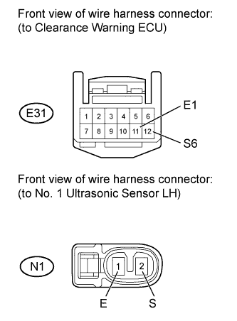
2. CHECK HARNESS AND CONNECTOR (CLEARANCE WARNING ECU - NO. 1 ULTRASONIC SENSOR LH)

  1. E160758E01
    Disconnect the E31 clearance warning ECU connector.

  1. Disconnect the N1 No. 1 ultrasonic sensor LH connector.

  1. Measure the resistance according to the value(s) in the table below.

    Standard Resistance:
    Tester Connection
    Condition
    Specified Condition
    E31-12 (S6) - N1-2 (S)
    Always
    Below 1 Ω
    E31-11 (E1) - N1-1 (E)
    Always
    Below 1 Ω
    E31-12 (S6) - Body ground
    Always
    10 kΩ or higher
    E31-11 (E1) - Body ground
    Always
    10 kΩ or higher

  1. Reconnect the clearance warning ECU connector.

  1. Reconnect the No. 1 ultrasonic sensor LH connector.


NG
REPAIR OR REPLACE HARNESS OR CONNECTOR
OK

PROCEED TO NEXT CIRCUIT INSPECTION SHOWN IN PROBLEM SYMPTOMS TABLE (Click here)


← Back Sonar Sensor LH Circuit (Jul 2007 – Oct 2010)Back Sonar Sensor RH Circuit (Jul 2007 – Oct 2010) →