Clutch Switch Circuit
Circuit diagnosis · Vehicles built Aug 2009 – Oct 2010
Versions by build date: Jul 2007 – Jul 2009 Aug 2009 – Oct 2010 from Nov 2010
DESCRIPTION
Clutch switch circuit inspection is necessary for M/T vehicles.When the clutch pedal is released, the ECM receives the positive (+) battery voltage through the ECU-IG fuse and ignition switch. While the clutch pedal is depressed, the clutch switch assembly sends a signal to terminal D of the ECM. The ECM cancels cruise control when terminal D receives the signal (voltage of below 1 V).
WIRING DIAGRAM
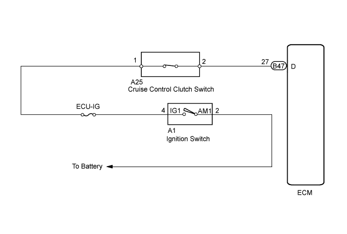

INSPECTION PROCEDURE
| 1. CHECK HARNESS AND CONNECTOR (ECM - BATTERY) |

Disconnect the B47 ECM connector.
Turn the ignition switch to the ON position.
Measure the voltage.
- Standard voltage:
Tester Connection
Clutch Pedal Condition
Specified Condition
D(B47-27) - Body ground
Depressed
Below 1 V
D(B47-27) - Body ground
Released
11 to 14 V
Reconnect the ECM connector.
|
|
||||

| NG | |
 |
| 2. INSPECT CLUTCH SWITCH ASSEMBLY |
Disconnect the clutch switch connector.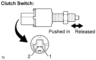
Measure the resistance.
- Standard resistance:
Tester Connection
Clutch Pedal Condition
Specified Condition
1 - 2
Switch pin free
(Clutch pedal depressed)
10 kΩ or higher
1 - 2
Switch pin pushed in
(Clutch pedal released)
Below 1 Ω
Reconnect the clutch switch connector.
|
|
||||
| OK | |
|
| 3. CHECK HARNESS AND CONNECTOR (CLUTCH SWITCH ASSEMBLY - ECM) |
Disconnect the B47 ECM connector.
Disconnect the A25 clutch switch connector.
Measure the resistance.
- Standard resistance:
Tester Connection
Specified Condition
A25-2 or D (B47-27) - Body ground
10 kΩ or higher
A25-2 - D (B47-27)
Below 1 Ω
Reconnect the clutch switch connector.
Reconnect the ECM connector.
|
|
||||
| OK | ||
 |
||
| ||