TERMINALS OF ECU
System information · Vehicles built Jul 2007 – Oct 2010
Versions by build date: Jul 2007 – Oct 2010 Nov 2010 – Jul 2014 Aug 2012 – Jul 2014 from Aug 2014
| INSPECT AIR CONDITIONING AMPLIFIER ASSEMBLY |
Disconnect the E32 and E33 connectors from the air conditioning amplifier assembly and inspect the connector on the wire harness side, as shown in the table below.
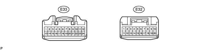

If the results are not as specified, inspect the circuits connected to the other parts.Standard: Symbols (Terminals No.)
Wiring Colors
Terminal Descriptions
Conditions
Specified Condition
IG+ (E32-1) - GND (E32-20)
Y-R - W-B
Power source (IG)
Ignition switch: OFF → ON
Below 1.0 → 11 to 14 V
B (E32-11) - GND (E32-20)
W-R - W-B
Power source (Back-up)
Always
11 to 14 V
SG-1 (E33 - 17) - Body ground
V-G - Body ground
Ground for mode control servo motor
Always
Below 1.0 Ω
SG-2 (E33 - 18) - Body ground
Y-G - Body ground
Ground for air mix control servomotor
Always
Below 1.0 Ω
SG-3 (E33 - 6) - Body ground
G-Y - Body ground
Ground for lock sensor
Always
Below 1.0 Ω
SG-4 (E32 - 9) - Body ground
GR-G - Body ground
Ground for A/C evaporator temperature sensor
Always
Below 1.0 Ω
TAMG (E33 - 16) - Body ground
GR - Body ground
Ground for ambient temperature sensor
Always
Below 1.0 Ω
GND (E32-20) - Body ground
W-B - Body ground
Ground for main power supply
Always
Below 1.0 Ω
Reconnect the E32 and E33 connectors to the air conditioning amplifier assembly and inspect the wire harness side connector from the back side, as shown in the table below.
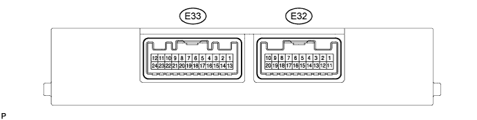
If the results are not as specified, replace the air conditioning amplifier assembly with a new one. If the results are still not as specified after replacing the air conditioning control assembly, inspect the circuits connected to other parts.Standard: Symbols (Terminals No.)
Wiring Colors
Terminal Descriptions
Conditions
Specified Condition
DEF (E33-9) - GND (E32-20)
LG - W-B
Mode switch signal
Ignition switch: ON
Mode select switch:
Except DEF → DEF
Below 1.5 → 11 to 14 V
LOCK (E33-8) - SG-3 (E33-6)
R-W - G-Y
Magnet clutch signal
Start engine
Operate A/C system
Magnet clutch: ON
Pulse generation
(See waveform 1)
ACI (E33-24) - GND (E32-20)
G-W - W-B
Idle up request signal
Engine idling
Operate A/C system
Magnet clutch: OFF → ON
11 to 14 → Below 1.0 V
FRS (E32-6) - GND (E32-20)
V-W - W-B
Recirculation/Fresh switch signal
Ignition switch: ON
Recirculation/Fresh switch:
RECIRCULATION → FRESH
11 to 14 → Below 1.0 V
REC (E32-7) - GND (E32-20)
P-B - W-B
Recirculation/Fresh switch signal
Ignition switch: ON
Recirculation/Fresh switch:
FRESH → RECIRCULATION
11 to 14 → Below 1.0 V
MGC (E32-4) - GND (E32-20)
LG-B - W-B
Magnet clutch relay signal
Engine idling
Operate A/C system
Magnet clutch: OFF → ON
11 to 14 → Below 1.0 V
PSW (E33-22) - GND (E32-20)
LG-R - W-B
A/C pressure switch signal
Start engine
Operate A/C system
Refrigerant pressure: Normal (Less than 0.196 MPa (2.0 kgf/cm2)) or more than 3.14 MPa (32.0 kgf/cm2))
11 to 14 → Below 1.0 V
BLW (E32-8) - GND (E32-20)
Y - W-B
Blower switch signal
Ignition switch: ON
Blower switch: ON
OFF → ON (LO, M1, M2, HI)
11 to 14 → Below 1.0 V
TE (E32-10) - SG-4 (E32-9)
B - GR-G
A/C evaporator temperature sensor signal
Ignition switch: ON
Evaporator temperature:
0 → 15°C (32 → 59°F)
1.7 to 2.1 → 0.9 to 1.3 V
TAM (E33-13) - TAMG (E33-16)
Y - GR
Ambient temperature sensor signall
Ignition switch: ON
Ambient temperature:
25 → 40°C (77 → 104°F)
1.7 to 2.1 → 1.3 to 1.8 V
RDFG (E32-5) - GND (E32-20)
Y-V - W-B
Defogger switch signal
Ignition switch: ON
Defogger switch: OFF → ON
11 to 14 → Below 1.0 V
S5 (E33-19) - SG-1 (E33-17)
P - V-G
Power supply for mode control servo motor
Ignition switch: OFF → ON
0 to 5.0 V
S5-1 (E33-7) - SG-2 (E33-18)
P-B - Y-G
Power supply for air mix control servomotor
Ignition switch: OFF → ON
0 to 5.0 V
SG-1 (E33 - 17) - Body ground
V-G - Body ground
Ground for mode control servo motor
Always
Below 1.0 Ω
SG-2 (E33 - 18) - Body ground
Y-G - Body ground
Ground for air mix control servomotor
Always
Below 1.0 Ω
SG-3 (E33 - 6) - Body ground
G-Y - Body ground
Ground for lock sensor
Always
Below 1.0 Ω
SG-4 (E32 - 9) - Body ground
GR-G - Body ground
Ground for A/C evaporator temperature sensor
Always
Below 1.0 Ω
TAMG (E33 - 16) - Body ground
GR - Body ground
Ground for ambient temperature sensor
Always
Below 1.0 Ω
GND (E32-20) - Body ground
W-B - Body ground
Ground for main power supply
Always
Below 1.0 Ω
IG+ (E32-1) - Body ground
Y-R - Body ground
Power source (IG)
Ignition switch: OFF → ON
Below 1.0 → 11 to 14 V
B (E32-11) - Body ground
W-R - Body ground
Power source (Back-up)
Always
11 to 14 V
WAVEFORM 1: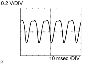
Magnet clutch signalECM Terminal Names
Between LOCK (E33-8) - SG-3 (E33-6)
Tester Ranges
0.2 V/DIV, 10 msec./DIV
Conditions
Idling
- HINT:
- The wavelength becomes shorter as the engine rpm increases.
| INSPECT ECM |
Connect the connector to the ECM and inspect the wire harness side connector from the back side, as shown in the table below.
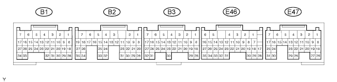
If the result is not as specified, the ECM may have a malfunction.Standard voltage: Symbols (Terminals No.)
Wiring Colors
Terminal Descriptions
Conditions
Specified Condition
ACT (E46-25) - E1 (B3-1)
L-W - BR
Magnet clutch ON
permit signal
Start engine
Operate A/C system
A/C switch OFF Blower switch OFF → A/C switch ON Blower switch ON
Below 1.0 → 11 to 14 V
AC1 (E46-24) - E1 (B3-1)
G-W - BR
Idle-up request signal
Start engine
A/C magnet clutch is engaged → not engaged
Below 1.0 → 11 to 14 V
THWO (E46-14) - E2 (B1-28)
BR-B - W-G
Engine coolant temperature sensor signal
Engine idling
Engine coolant temperature 80°C (176°F)
Pulse generation
(See waveform 1)
WAVEFORM 1: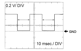
Magnet clutch signalECM Terminal Names
Between THWO (E46-14) - E2 (B1-28)
Tester Ranges
0.2 V/DIV, 10 msec./DIV
Conditions
Idling
- HINT:
- The wavelength becomes shorter as the engine rpm increases.