INSPECTION
Inspection · Vehicles built Jul 2007 – Jul 2009
Versions by build date: Jul 2007 – Jul 2009 from Aug 2009
| INSPECT CYLINDER HEAD SET BOLT |

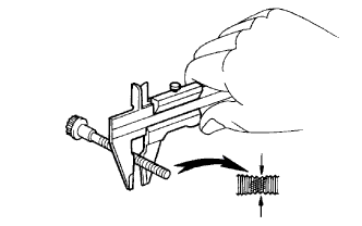  |
Using vernier calipers, measure the outer diameter of the cylinder head set bolt thread.
- Standard outer diameter:
- 10.85 to 11.00 mm (0.4272 to 0.4331 in.)
- Minimum outer diameter:
- 10.7 mm (0.421 in.)
| CLEAN CYLINDER HEAD SUB-ASSEMBLY |
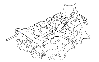 |
Using a gasket scraper, remove all the gasket material from the cylinder block contact surface.
- NOTICE:
- Be careful not to scratch the cylinder block contact surface.
Using a wire brush, remove all the carbon from the combustion chambers.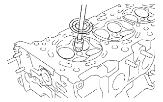
- NOTICE:
- Be careful not to scratch the combustion chambers.
Using a valve guide bushing brush and solvent, clean all the valve guide bushes.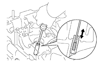
Using a soft brush and solvent, thoroughly clean the cylinder head.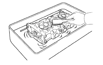
| INSPECT CYLINDER HEAD SUB-ASSEMBLY |
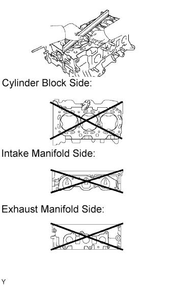 |
Inspect the cylinder head for warpage.
Using a precision straight edge and feeler gauge, measure the warpage on the cylinder block side and the intake and exhaust sides.
- Maximum warpage:
- 0.10 mm (0.0039 in.)
Inspect the cylinder head for cracks.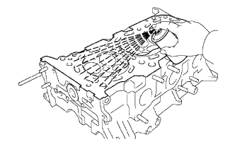
Using a dye penetrant, check the combustion chamber, intake ports, exhaust ports and cylinder block surface for cracks.
If cracked, replace the cylinder head.
| CLEAN VALVE |
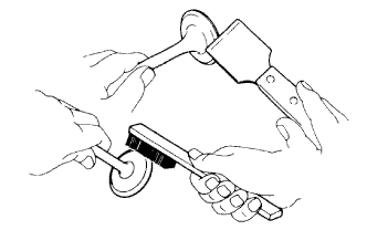 |
Using a gasket scraper, chip off any carbon from the valve head.
Using a wire brush, thoroughly clean the valve.
| INSPECT VALVE |
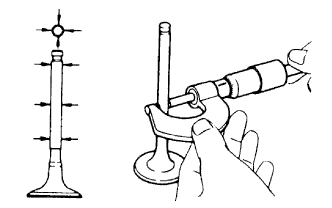 |
Inspect the valve stem diameter.
Using a micrometer, measure the diameter of the valve stem.
- Valve stem diameter:
Valve Stem
Specification
Intake
5.470 to 5.485 mm (0.2154 to 0.2159 in.)
Exhaust
5.465 to 5.480 mm (0.2152 to 0.2158 in.)
Inspect the valve face angle.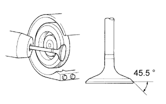
Grind the valve enough to remove any pits and carbon.
Check that the valve is ground to the correct valve face angle.
- Valve face angle:
- 45.5°
Inspect the valve head margin thickness.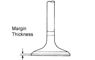
Using vernier calipers, check the valve head margin thickness.
- Standard margin thickness:
- 1.0 mm (0.039 in.)
- Minimum margin thickness:
- 0.5 mm (0.020 in.)
Inspect the overall length.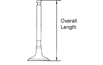
Using vernier calipers, check the overall length.
- Standard overall length:
Valve
Specification
Intake
106.95 mm (4.2106 in.)
Exhaust
105.80 mm (4.1654 in.)
- Minimum overall length:
Valve
Specification
Intake
106.70 mm (4.2008 in.)
Exhaust
105.55 mm (4.1555 in.)
Inspect the valve stem tip.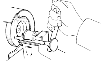
Check the surface of the valve stem tip for wear.
- NOTICE:
- Do not grind to less than the minimum length.
| CLEAN VALVE SEAT |
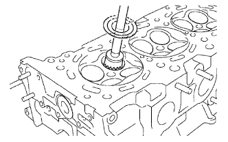 |
Using a 45° carbide cutter, resurface the valve seats.
Clean the valve seats.
| INSPECT VALVE SEAT |
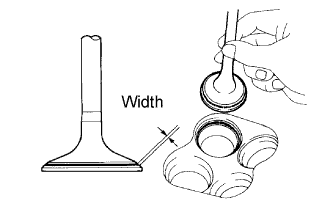 |
Apply a light coat of prussian blue to the valve face.
Lightly press the valve against the valve seat.
- NOTICE:
- Do not rotate the valve.
Check the valve face and seat according to the following procedure.
If blue appears 360° around the face, the valve is concentric.
If not, replace the valve.If the blue appears 360° around the valve seat, the guide and face are concentric.
If not, resurface the valve seat.Check that the seat is in contact with the middle of the valve face with the following width.
- Standard width:
- 1.0 to 1.4 mm (0.039 to 0.055 in.)
| INSPECT INNER COMPRESSION SPRING |
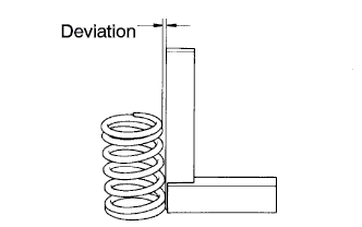 |
Inspect the deviation.
Using steel squares, measure the deviation of the inner compression spring.
- Maximum deviation:
- 2.0 mm (0.079 in.)
Inspect the free length.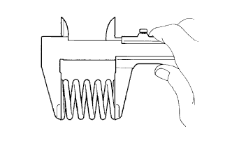
Using vernier calipers, measure the free length of the inner compression spring.
- Free length:
- 47.80 mm (1.8819 in.)
Inspect the tension.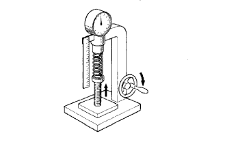
Using a spring tester, measure the tension of the inner compression spring at the specified installed length.
- Installed tension:
Installed Length
Specification
33.3 mm (1.311 in.)
186.2 to 205.8 N (19.0 to 21.0 kgf, 41.9 to 46.3 lbf)
| INSPECT VALVE GUIDE BUSH OIL CLEARANCE |
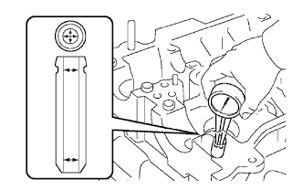 |
Using a caliper gauge, measure the internal diameter of the valve guide bush.
- Inside diameter:
- 5.51 to 5.53 mm (0.2169 to 0.2177 in.)
Subtract the valve stem diameter measurement from the valve guide bush internal diameter measurement.
- Standard oil clearance:
Valve Guide Bush
Specification
Intake
0.025 to 0.060 mm (0.0010 to 0.0024 in.)
Exhaust
0.030 to 0.065 mm (0.0012 to 0.0026 in.)
- Maximum oil clearance:
Valve Guide Bush
Specification
Intake
0.08 mm (0.0031 in.)
Exhaust
0.10 mm (0.0039 in..)
| INSPECT VALVE LIFTER |
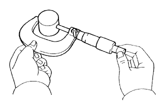 |
Using a micrometer, measure the valve lifter diameter.
- Valve lifter diameter:
- 30.966 to 30.976 mm (1.2191 to 1.2195 in.)
| INSPECT VALVE LIFTER OIL CLEARANCE |
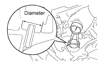 |
Using a caliper gauge, measure the lifter bore diameter of the cylinder head.
- Lifter bore diameter:
- 31.009 to 31.025 mm (1.2208 to 1.2215 in.)
Subtract the valve lifter diameter measurement (Step 16) from the lifter bore diameter measurement.
- Standard oil clearance:
- 0.033 to 0.059 mm (0.0013 to 0.0023 in.)
- Maximum oil clearance:
- 0.08 mm (0.0031 in.)
If necessary, replace the cylinder head.