Circuit diagnosis · Vehicles built Jul 2007 – Jul 2009
Versions by build date: Jul 2007 – Jul 2009from Aug 2009
DESCRIPTION
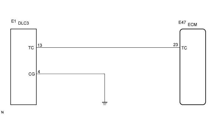
The DLC3 circuit enables reading of Diagnostic Trouble Codes (DTCs) without using intelligent testers by connecting terminals TC and CG of the DLC3 connector. Stored DTCs are displayed in blinking patterns of the CRUISE MAIN indicator light located on the combination meter.
WIRING DIAGRAM
HINT:
When a particular warning light blinks continuously, a ground short in the wiring of terminal TC of the DLC3 or an internal ground short in the relevant ECU is suspected.
INSPECTION PROCEDURE
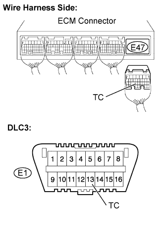
1. CHECK HARNESS AND CONNECTOR (TC of DLC3 - ECM)
Disconnect the E47 connector of the ECM.
Measure the resistance.
Standard resistance:
Tester Connection
Specified Condition
TC (E1-13) - TC (E47-23)
Below 1 Ω
Reconnect the ECM connector.
NG
REPAIR OR REPLACE HARNESS OR CONNECTOR (TC of DLC3 - ECM)
OK
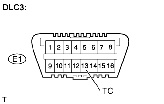
2. CHECK HARNESS AND CONNECTOR (TC of DLC3 - BODY GROUND)
Measure the resistance.
Standard resistance:
Tester Connection
Specified Condition
TC (E1-13) - Body ground
10 kΩ or higher
NG
REPAIR OR REPLACE HARNESS OR CONNECTOR (TC CIRCUIT)
OK
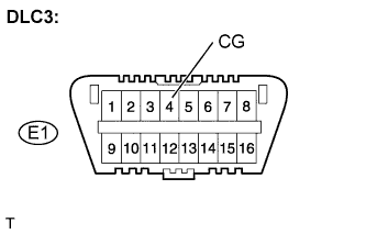
3. CHECK HARNESS AND CONNECTOR (CG of DLC3 - BODY GROUND)
Measure the resistance.
Standard resistance:
Tester Connection
Specified Condition
CG (E1-4) - Body ground
Below 1 Ω
NG
REPAIR OR REPLACE HARNESS OR CONNECTOR (CG of DLC3 - BODY GROUND)