ON-VEHICLE INSPECTION
Inspection · Vehicles built Jul 2007 – Oct 2012
Versions by build date: Jul 2007 – Oct 2012 from Nov 2012
| REMOVE FRONT WHEEL |
| REMOVE FRONT DISC BRAKE CALIPER ASSEMBLY |

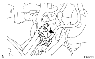  |
Remove the bolt and separate the brake tube bracket from the steering knuckle.
Using SST, separate the brake tube from the disc brake cylinder.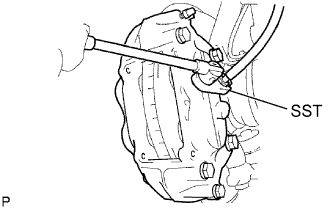
- SST
- 09023-00101
- HINT:
- Use a container to collect the brake fluid as it drains out.
Remove the 2 bolts and disc brake caliper assembly.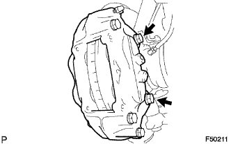
| REMOVE FRONT DISC |
Place matchmarks on the disc and the axle hub and remove the disc.
| REMOVE FRONT AXLE HUB GREASE CAP |
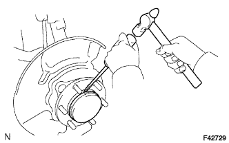 |
Using a screwdriver and a hammer, remove the front axle hub grease cap.
- NOTICE:
- Do not damage the axle hub.
| INSPECT FRONT AXLE HUB BEARING |
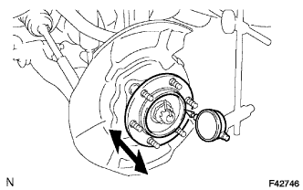 |
Inspect the axle hub backlash.
Using a dial indicator, check the backlash near the center of the axle hub.
- Maximum:
- 0.05 mm (0.0020 in.)
Inspect the axle hub runout.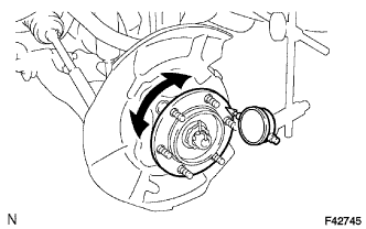
Using a dial indicator, check the runout of the surface of the axle hub.
- Maximum:
- 0.05 mm (0.0020 in.)
| INSTALL FRONT AXLE HUB GREASE CAP |
| INSTALL FRONT DISC |
Align the matchmarks of the disc and axle hub and install the disc.
- HINT:
- When replacing the disc, select the position that gives the minimum disc runout.
| INSTALL FRONT DISC BRAKE CALIPER ASSEMBLY |
|
|
Install the front disc brake caliper assembly with the 2 bolts.
- Torque:
- 123 N*m{ 1,254 kgf*cm , 91 ft.*lbf }
Install the brake tube bracket onto the steering knuckle with the bolt.
- Torque:
- 29 N*m{ 296 kgf*cm , 21 ft.*lbf }
Using SST, install the brake tube onto the disc brake cylinder.
- SST
- 09023-00101
- Torque:
- for use without SST:
- 15 N*m{ 155 kgf*cm , 11 ft.*lbf }
- for use with SST:
- 14 N*m{ 143 kgf*cm , 10 ft.*lbf }
- HINT:
- Use a torque wrench with a fulcrum length of 300 mm (11.81 in.).
- This torque value is effective when SST is parallel to the torque wrench.
- Use a torque wrench with a fulcrum length of 300 mm (11.81 in.).
| BLEED BRAKE LINE |
Turn the ignition switch to ON.
Remove the brake master cylinder reservoir filler cap assembly.
Add brake fluid until the fluid level is between the MIN and MAX lines of the reservoir.
Repeatedly depress the brake pedal and bleed air from the bleeder plug of the front disc brake cylinder RH.
Repeat the step above until the air is completely bled, and then tighten the bleeder plug while depressing the brake pedal.
- Torque:
- 11 N*m{ 110 kgf*cm , 8 ft.*lbf }
Bleed the air from the bleeder plug of the front disc brake cylinder LH using the same procedure as for the RH side.
With the brake pedal depressed, loosen the bleeder plug of the rear disc brake cylinder RH, continue to hold the brake pedal and allow brake fluid to be drained from the bleeder plug while the pump motor operates.
- HINT:
- Air is bled as the pump motor operates while the brake pedal is being depressed.
- Be sure to release the brake pedal to stop the motor after approximately 100 seconds of continuous operation.
- As brake fluid is continuously drained while the pump operates, it is not necessary to repeatedly depress the brake pedal.
- Air is bled as the pump motor operates while the brake pedal is being depressed.
When there is no more air in the brake fluid, tighten the bleeder plug, and then release the brake pedal.
- Torque:
- 11 N*m{ 110 kgf*cm , 8 ft.*lbf }
Bleed the air from the bleeder plug of the rear disc brake cylinder LH using the same procedure as for the RH side.
Turn the ignition switch off.
Inspect for brake fluid leaks.
Check and adjust the brake fluid level (Click here).
Clear the DTCs (Click here).
| INSTALL FRONT WHEEL |
- Torque:
- 112 N*m{ 1,137 kgf*cm , 82 ft.*lbf }
| REMOVE REAR WHEEL |
| SEPARATE REAR DISC BRAKE CALIPER ASSEMBLY |
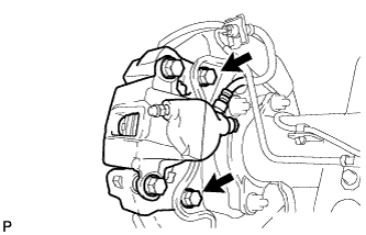 |
Remove the 2 bolts and 2 washers and separate the disc brake caliper assembly.
- NOTICE:
- Suspend the disc brake caliper assembly with a piece of rope.
| REMOVE REAR DISC |
Release the parking brake lever.
Place matchmarks on the disc and axle hub and remove the disc.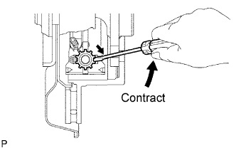
- HINT:
- If the disc cannot be removed easily, turn the shoe adjuster until the wheel turns freely.
| INSPECT REAR AXLE SHAFT BEARING |
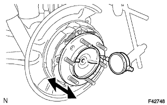 |
Inspect the axle shaft backlash.
Using a dial indicator, check the backlash near the center of the axle shaft.
- Maximum:
- 0.05 mm (0.0020 in.)
Inspect the axle shaft runout.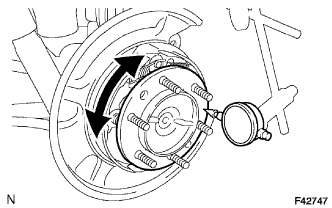
Using a dial indicator, check the runout of the surface of the axle shaft.
- Maximum:
- 0.05 mm (0.0020 in.)
| INSTALL REAR DISC |
Align the matchmarks of the disc and axle hub and install the disc.
| ADJUST PARKING BRAKE SHOE CLEARANCE |
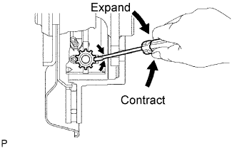 |
Provisionally install the 2 hub nuts.
Remove the hole plug, and turn the adjuster to expand the shoe until the disc locks.
Contract the shoe adjuster until the disc rotates smoothly.
- Standard:
- Return 8 notches
Install the hole plug.
| INSTALL REAR DISC BRAKE CALIPER ASSEMBLY |
|
|
Install the disc brake caliper with the 2 bolts and 2 washers.
- Torque:
- 105 N*m{ 1,071 kgf*cm , 78 ft.*lbf }
| INSTALL REAR WHEEL |
- Torque:
- 112 N*m{ 1,137 kgf*cm , 82 ft.*lbf }