2011-2016 FJ Cruiser · Service Manual BODY ELECTRICAL

REMOVAL

Removal / installation · Vehicles built from Nov 2010

Versions by build date: Jul 2007 – Oct 2010 from Nov 2010


1. REMOVE PARKING BRAKE HOLE COVER SUB-ASSEMBLY

  1. B271473
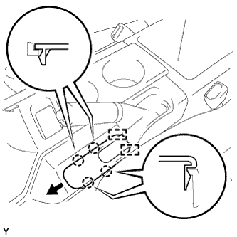
    Disengage the 4 claws.

  1. Slide the parking brake hole cover toward the front of the vehicle, disengage the 2 guides and remove the parking brake hole cover.


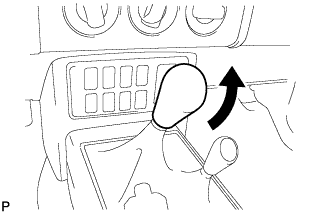
2. REMOVE SHIFT LEVER KNOB SUB-ASSEMBLY (for Manual Transmission)

  1. B133893
    Remove the shift lever knob.


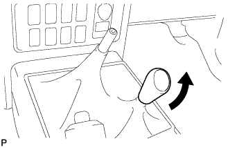
3. REMOVE SHIFT LEVER KNOB SUB-ASSEMBLY (for 4WD)

  1. B133895
    Remove the shift lever knob.


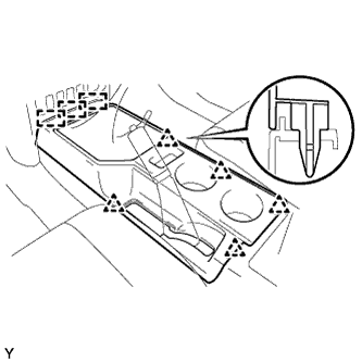
4. REMOVE CONSOLE UPPER REAR PANEL SUB-ASSEMBLY

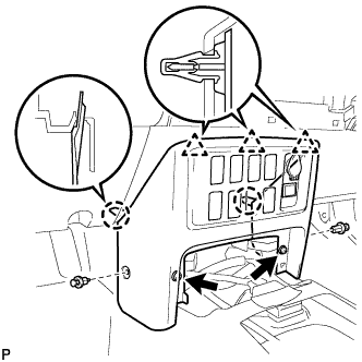
  1. B271474
    Shift the shift lever into the N position.

  1. Disengage the 5 clips and 3 guides and remove the console upper rear panel.


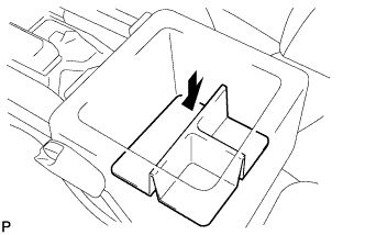
5. REMOVE BOX BOTTOM MAT

  1. B133899
    Remove the box bottom mat.


6. REMOVE FRONT CONSOLE BOX

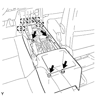
  1. B271475
    Remove the 4 <H> bolts.

  1. Disengage the 5 guides and remove the console box.


7. REMOVE CONSOLE UPPER PANEL NO. 1 GARNISH (for RHD)

  1. B267053
    Disengage claw and the 2 clips.

  1. Slide the console upper panel garnish toward the rear of the vehicle, disengage the guide and remove the console upper panel garnish.


8. REMOVE INSTRUMENT LOWER COVER SUB-ASSEMBLY

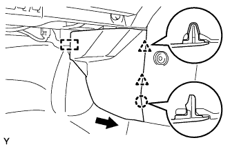
  1. B133852
    Remove the 2 clips and 2 <E> bolts.

  1. Disengage the 3 clips and 2 claws and remove the instrument lower cover.


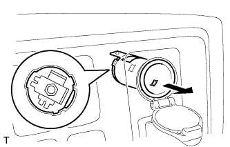
9. REMOVE POWER OUTLET SOCKET (for LHD)

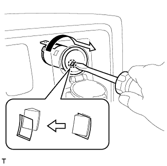
  1. E127824
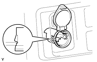
    Using a screwdriver, disengage the claw, then turn the power outlet socket counterclockwise and push the power outlet socket half way out.

  1. E127825
    Align the protrusion of the power outlet socket with the cutout of the power outlet socket cover and then push the power outlet socket out.


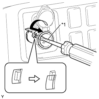
10. REMOVE POWER OUTLET SOCKET (for RHD)

  1. E218446E01
    Using a screwdriver with its tip wrapped in protective tape, disengage the claw, then turn the power outlet socket counterclockwise and push the power outlet socket half way out.
    Text in Illustration  
    *1
    Protective Tape

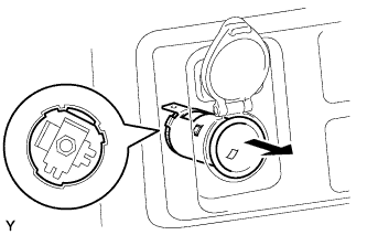
  1. E218447
    Align the protrusion of the power outlet socket with the cutout of the power outlet socket cover and then push the power outlet socket out.


11. REMOVE POWER OUTLET SOCKET COVER NO.2 (for LHD)

  1. E127826
    Disengage the 2 claws and remove the power outlet socket cover.


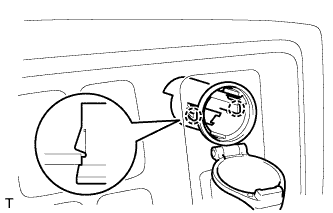
12. REMOVE POWER OUTLET SOCKET COVER NO.2 (for RHD)

  1. E218448
    Disengage the 2 claws and remove the power outlet socket cover.
← REMOVAL (Jul 2007 – Oct 2010)INSTALLATION (Jul 2007 – Oct 2010) →