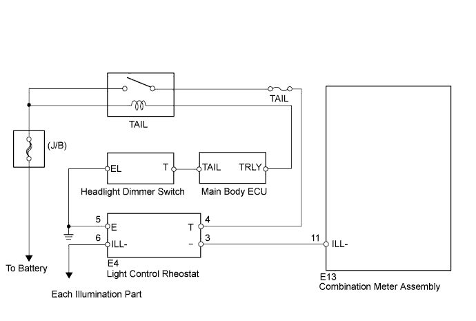
The combination meter assembly controls the combination meter illumination in accordance with the light control signals from the light control rheostat.
WIRING DIAGRAM
INSPECTION PROCEDURE
1. INSPECT FUSE (TAIL)
Remove the TAIL fuse from the main body ECU.
Measure the resistance.
Standard resistance:
Below 1 Ω
Reinstall the TAIL fuse.
NG
REPLACE FUSE
OK
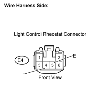
2. CHECK HARNESS AND CONNECTOR (FUSE (TAIL) - RHEOSTAT, RHEOSTAT - BODY GROUND)
Disconnect the E4 light control rheostat connector.
Measure the voltage and resistance.
Standard:
Tester Connection
Condition
Specified Condition
E4-4 (T) - Body ground
Tail light ON
11 to 14V
E4-5 (E) - Body ground
Always
Below 1 Ω
Reconnect the light control rheostat connector.
NG
REPAIR OR REPLACE HARNESS OR CONNECTOR
OK
3. INSPECT LIGHT CONTROL RHEOSTAT
Remove the light control rheostat but without disconnecting the connector.
Turn the ignition switch ON.
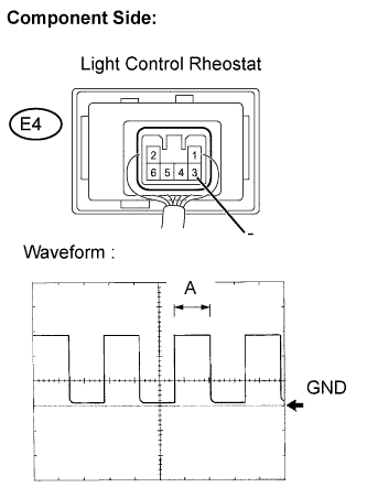
Using an oscilloscope, check the signal waveform of the light control rheostat.
Item
Contents
Terminal connection
E4-3 (-) - Body ground
Tool setting
5V / DIV, 50ms / DIV
Vehicle condition
Ignition switch ON
OK:
Waveform is as shown in the illustration.
HINT:
Duty ratio changes as the illumination dims. (A becomes longer)