INSTALLATION
Removal / installation · Vehicles built Nov 2010 – Jul 2012
Versions by build date: Jul 2007 – Oct 2010 Nov 2010 – Jul 2012 from Aug 2012
| 1.
INSTALL ROOF HEADLINING |
 |
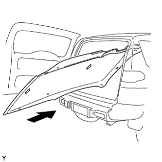
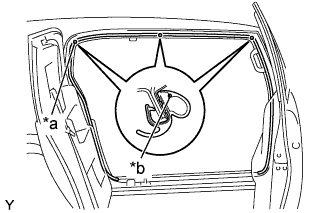
- Pull the roof headlining back into the vehicle through the back door.
Install the 4 clips.
for LHD:
Install the 4 clamps.
Install the clamp.
Connect the 2 connectors.
Insert the wire harness into the 2 clamps.
for RHD:
Install the 3 clamps.
Connect the 2 connectors.
Insert the wire harness into the 2 clamps.
| 2.
INSTALL LOWER INSTRUMENT PANEL FINISH PANEL (for LHD)
|
|
Engage the 5 clips and claw and install the lower instrument panel finish panel.
Install the 2 <E> bolts.
| 3.
INSTALL HOOD LOCK CONTROL LEVER SUB-ASSEMBLY (for LHD)
|
|
Engage the 3 claws and install the hood lock control lever.
| 4.
INSTALL NO. 1 INSTRUMENT PANEL REGISTER ASSEMBLY (for LHD)
|
|
Engage the 4 clips and 2 claws and install the instrument panel register.
| 5.
INSTALL INSTRUMENT PANEL LOWER FINISH PANEL SUB-ASSEMBLY (for RHD)
|
|
Install the connectors to the instrument panel lower finish panel.
Engage the claw and 2 clips and install the instrument panel lower finish panel.
Install the screw <A>.
| 6.
INSTALL GLOVE COMPARTMENT DOOR ASSEMBLY (for RHD)
|
|
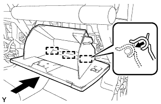
- Install the glove compartment door assembly with the 3 hinges while holding it horizontal.
Slightly flex the upper part of the glove compartment door assembly, and install the glove compartment door assembly.
Install the glove compartment door stoppers onto the glove compartment door.
| 7.
INSTALL PERSONAL LIGHT ASSEMBLY |
|
- Connect the connector.
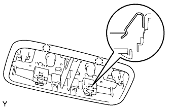
Engage the 4 claws and install the personal light.
| 8.
INSTALL NO. 1 PERSONAL LIGHT LENS |
|
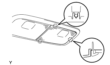
- Engage the 3 claws and install the No. 1 personal light lens.
| 9.
INSTALL NO. 2 PERSONAL LIGHT LENS |
|
- HINT:
- Perform the same procedure as for the RH side.
| 10.
INSTALL ROOM LIGHT ASSEMBLY |
|
- HINT:
- The procedure described below is for the front side. Use the same procedure for both the front and rear sides, unless otherwise specified.
- for Front Side:
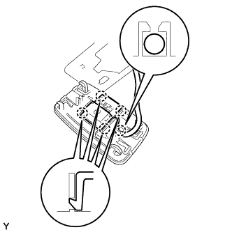
Engage the 4 claws and install the room light switch base.
Insert the 2 wire harnesses into the 2 claws of the room light.
- for Rear Side:
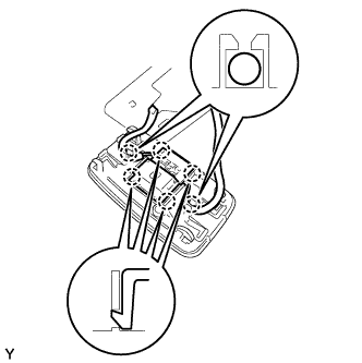
Engage the 4 claws and install the room light switch base.
Insert the wire harness into the claw of the room light.
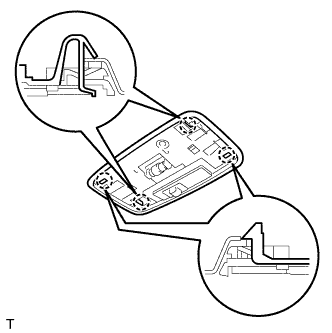
- Engage the 4 claws and install the room light.
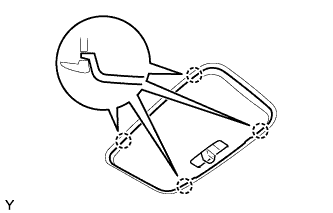
- Engage the 4 claws and install the room light lens.
| 11.
INSTALL INNER REAR VIEW MIRROR ASSEMBLY (w/ EC Mirror) |
|
(Click here)
| 12.
INSTALL INNER REAR VIEW MIRROR ASSEMBLY (w/o EC Mirror) |
|
(Click here)
| 13.
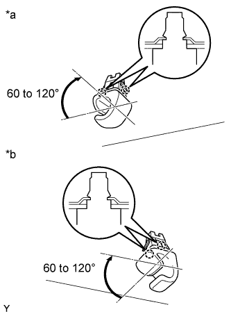
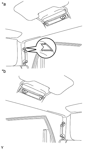
INSTALL VISOR HOLDER |
|
- HINT:
- Use the same procedure for both sides.
Text in Illustration
*a
|
for RH Side
|
*b
|
for LH Side
|
Engage the 2 claws by turning the visor holder clockwise between 60 to 120°and install the visor holder.
| 14.
INSTALL VISOR ASSEMBLY RH |
|
Install the visor with the 2 screws.
Install the visor support shaft into the visor holder.
| 15.
INSTALL VISOR ASSEMBLY LH |
|
- HINT:
- Use the same procedure as for the RH side.
| 16.
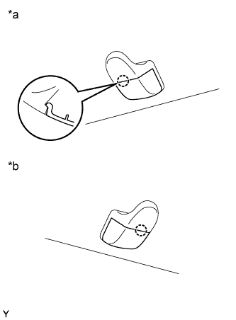
INSTALL COAT HOOK |
|
- HINT:
- Use the same procedure for both sides.
Install the coat hook with the bolt.
-
Torque:
- 8.0 N*m{
82 kgf*cm
, 71 in.*lbf
}
- Engage the claw and close the cover.
Text in Illustration
*a
|
for RH Side
|
*b
|
for LH Side
|
| 17.
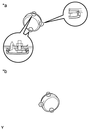
INSTALL ROOF HEADLINING HOLE PLUG |
|
- HINT:
- Use the same procedure for both sides.
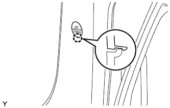
Engage the claw and install the roof headlining hole plug.
Tighten the bolt.
-
Torque:
- 5.5 N*m{
56 kgf*cm
, 49 in.*lbf
}
- Engage the 3 claws and close the cover.
Text in Illustration
*a
|
for RH Side
|
*b
|
for LH Side
|
| 18.
INSTALL ROOF SIDE INNER GARNISH RH |
|
Pass the rear seat outer belt through the slit in the roof side inner garnish.
Engage the 7 clips and the guide and install the roof side inner garnish.
Tighten the bolt.
-
Torque:
- 5.5 N*m{
56 kgf*cm
, 49 in.*lbf
}
Install the clip.
- Engage the claw and close the cover.
| 19.
INSTALL ROOF SIDE INNER GARNISH LH |
|
- HINT:
- Use the same procedure as for the RH side.
| 20.
INSTALL DECK TRIM SIDE PANEL ASSEMBLY RH |
|
Engage the 6 clips and the 8 claws and install the deck trim side panel.
Tighten the 3 screws.
Tighten the bolt.
-
Torque:
- 5.5 N*m{
56 kgf*cm
, 49 in.*lbf
}
| 21.
INSTALL DECK TRIM SIDE PANEL ASSEMBLY LH |
|
Engage the 6 clips and the 8 claws and install the deck trim side panel.
Tighten the 3 screws.
| 22.
INSTALL REAR SEAT OUTER BELT ASSEMBLY RH |
|
Install the anchor plate with the bolt.
-
Torque:
- 42 N*m{
428 kgf*cm
, 31 ft.*lbf
}
Make sure that the anchor plate rotates smoothly.
| 23.
INSTALL REAR SEAT OUTER BELT ASSEMBLY LH |
|
- HINT:
- Use the same procedure as for the RH side.
| 24.
INSTALL LAP BELT OUTER ANCHOR COVER |
|
- HINT:
- Use the same procedure for both sides.
Engage the 3 claws and install the lap belt outer anchor cover.
| 25.
INSTALL AMPLIFIER BOX SPEAKER ASSEMBLY (w/ Woofer)
|
|
Install the amplifier box speaker with the 4 screws.
-
Torque:
- 8.1 N*m{
83 kgf*cm
, 72 in.*lbf
}
Connect the connectors.
| 26.
INSTALL SPEAKER MOUNTING COVER (w/ Woofer)
|
|
Engage the 8 clips and 2 guides and install the speaker mounting cover.
| 27.
INSTALL DECK SIDE GARNISH (w/ Woofer) |
|
Engage the 6 claws and install the deck side garnish.
| 28.
INSTALL QUARTER TRIM POCKET (w/o Woofer) |
|
Engage the 6 claws and install the quarter trim pocket.
| 29.
INSTALL SIDE TRIM COVER (w/o Woofer) |
|
Engage the 6 claws and the 2 guides and install the side trim cover.
| 30.
INSTALL QUARTER TRIM POCKET TRAY (w/o Woofer) |
|
Engage the 7 claws and install the quarter trim pocket tray.
| 31.
INSTALL PACKAGE HOLDER NET HOOK |
|
- HINT:
- Use the same procedure to install all the package holder net hooks.
Install the package holder net hook with the bolt.
-
Torque:
- 8.1 N*m{
83 kgf*cm
, 72 in.*lbf
}
| 32.
INSTALL FRONT PILLAR GARNISH RH |
|
w/ Assist Grip:
Engage the guide and the 2 clips and install the front pillar garnish.
w/o Assist Grip:
Engage the guide and the 2 clips and install the front pillar garnish.
Tighten the bolt.
- Engage the claw and close the cover.
| 33.
INSTALL FRONT PILLAR GARNISH LH |
|
- HINT:
- Use the same procedure as for the RH side.
| 34.
INSTALL VISOR SUB-ASSEMBLY RH |
|
Engage the 2 claws and install the visor sub-assembly.
| 35.
INSTALL VISOR SUB-ASSEMBLY LH |
|
- HINT:
- Use the same procedure as for the RH side.
| 36.
INSTALL ASSIST GRIP ASSEMBLY |
|
- HINT:
- Use the same procedure to install all the assist grips.
Install the assist grip with the 2 bolts.
-
Torque:
- 8.0 N*m{
82 kgf*cm
, 71 in.*lbf
}
| 37.
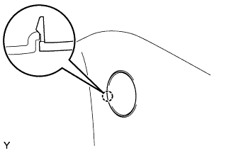
INSTALL ASSIST GRIP PLUG |
|
- HINT:
- Use the same procedure to install all the assist grip plugs.
Text in Illustration
*a
|
for RH Side
|
*b
|
for LH Side
|
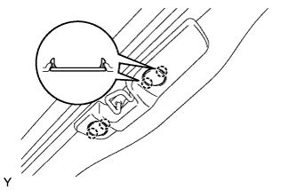
Engage the 2 claws and install the assist grip plug.
| 38.
INSTALL FRONT DOOR OPENING TRIM WEATHERSTRIP RH |
|
- Align the locating marks with the paint marks first, and install the front door opening trim weatherstrip, as shown in the illustration.
Text in Illustration
*a
|
Locating Mark
|
*b
|
Paint Mark
|
- Paint mark:
Area
|
Color
|
RH side
|
White
|
LH side
|
Red
|
| 39.
INSTALL FRONT DOOR OPENING TRIM WEATHERSTRIP LH |
|
- HINT:
- Use the same procedure as for the RH side.
| 40.
INSTALL ROOF SIDE RAIL GARNISH RH |
|
Engage the guide and the claws and install the roof side rail garnish.
Tighten the 2 bolts.
| 41.
INSTALL ROOF SIDE RAIL GARNISH LH |
|
- HINT:
- Use the same procedure as for the RH side.
| 42.
INSTALL ROOF SIDE INNER GARNISH COVER RH |
|
- HINT:
- Use the same procedure for both sides.
Engage the 2 claws and install the roof side inner garnish cover.
| 43.
INSTALL ROOF SIDE INNER GARNISH COVER LH |
|
- HINT:
- Use the same procedure as for the RH side.
| 44.
INSTALL COWL SIDE TRIM BOARD RH |
|
Engage the 2 claws and install the cowl side trim board.
Install the clip.
| 45.
INSTALL COWL SIDE TRIM BOARD LH |
|
- HINT:
- Use the same procedure as for the RH side.
| 46.
INSTALL FOOTREST CLIP (for LHD)
|
|
- HINT:
- Use the same procedure for both sides.
Engage the 2 claws and install the footrest clip.
| 47.
INSTALL FRONT FLOOR FOOTREST (for LHD)
|
|
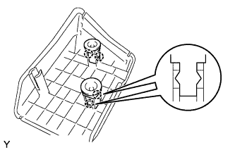
- Engage the 2 studs and install the front floor footrest.
| 48.
INSTALL ACCESS DOOR SCUFF PLATE RH |
|
Engage the 6 claws and install the access door scuff plate.
| 49.
INSTALL ACCESS DOOR SCUFF PLATE LH |
|
- HINT:
- Use the same procedure as for the RH side.
| 50.
INSTALL FRONT DOOR SCUFF PLATE RH |
|
Engage the 14 claws and install the door scuff plate.
| 51.
INSTALL FRONT DOOR SCUFF PLATE LH |
|
- HINT:
- Use the same procedure as for the RH side.
| 52.
INSTALL REAR FLOOR MAT ASSEMBLY |
|
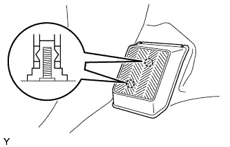
Install the rear floor mat with the 2 clips.
| 53.
INSTALL LUGGAGE HOLD BELT STRIKER ASSEMBLY |
|
- HINT:
- Use the same procedure for both sides.
Install the luggage hold belt striker with the bolt.
-
Torque:
- 18 N*m{
184 kgf*cm
, 13 ft.*lbf
}
Install the cap.
| 54.
INSTALL REAR FLOOR MAT SUPPORT PLATE |
|
Engage the 11 claws and install the rear floor mat support plate.
Tighten the 5 screws.
| 55.
INSTALL REAR FLOOR BOARD |
|
Engage the clip and claw and install the rear floor board.
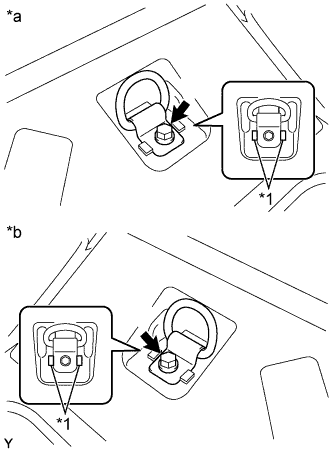
- Install the luggage hold belt striker with the bolt.
Text in Illustration
*1
|
Guide
|
*a
|
for RH Side
|
*b
|
for LH Side
|
-
Torque:
- 18 N*m{
184 kgf*cm
, 13 ft.*lbf
}
- HINT:
- Use the same procedure for both sides.
| 56.
INSTALL REAR SEATBACK ASSEMBLY RH
|
|
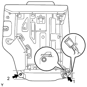
- Engage the hook and temporarily install the rear seatback with the 2 bolts.
Tighten the 2 bolts in the sequence shown in the illustration.
-
Torque:
- 37 N*m{
375 kgf*cm
, 27 ft.*lbf
}
Pull up the rear seatback.
- Install the rear seat inner belt into the rear seatback holder.
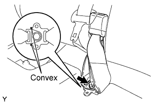
Install the anchor plate of the rear center seat outer belt with the bolt.
-
Torque:
- 42 N*m{
428 kgf*cm
, 31 ft.*lbf
}
- NOTICE:
- Do not place the anchor plate over the convex area of the rear seat inner belt.
| 57.
INSTALL REAR SEATBACK BOARD CARPET ASSEMBLY RH
|
|
- Pull the rear seatback lock release button and tilt the rear seatback forward.
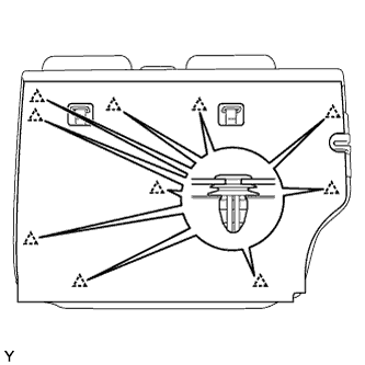
Engage the 10 clips and install the rear seatback board carpet.
Pull up the rear seatback.
| 58.
INSTALL REAR SEATBACK ASSEMBLY LH
|
|
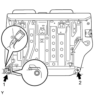
- Engage the hook and temporarily install the rear seatback with the 2 bolts.
Tighten the 2 bolts in the sequence shown in the illustration.
-
Torque:
- 37 N*m{
375 kgf*cm
, 27 ft.*lbf
}
Install the rear center seat inner belt into the rear seatback holder.
| 59.
INSTALL REAR SEATBACK BOARD CARPET ASSEMBLY LH
|
|
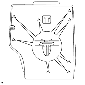
- Engage the 8 clips and install the rear seatback board carpet.
Pull up the rear seatback.