INSTALLATION
Removal / installation · Vehicles built Jul 2007 – Oct 2010
Versions by build date: Jul 2007 – Oct 2010 Nov 2010 – Jul 2012 from Aug 2012
| 1.
INSTALL ROOF HEADLINING |
 |
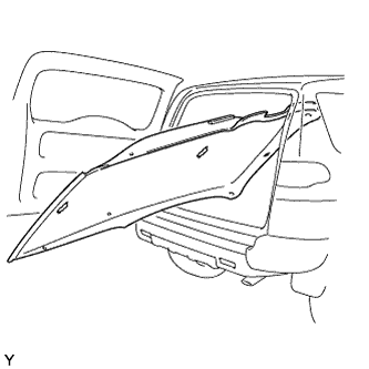
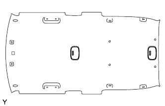
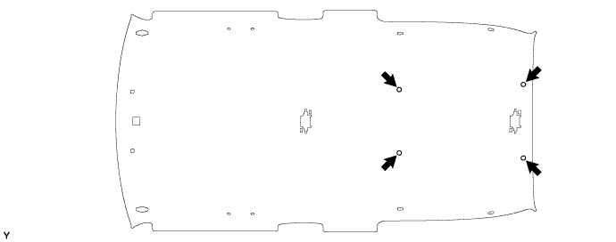
- Pull the roof headlining back into the vehicle through the back door.
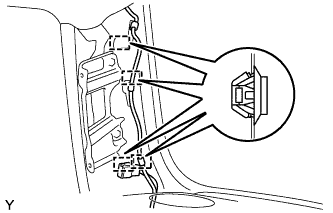
Install the 4 clips.

- Install the 3 clamps and the connector.
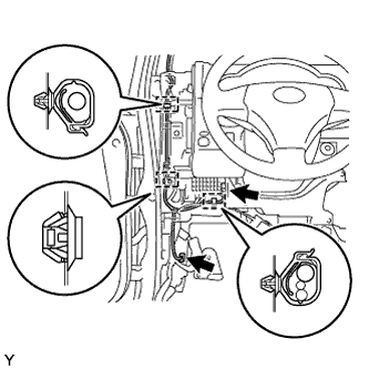
- Install the clamp.
Connect the 2 connectors.
Insert the wire harness into the 2 clamps.
| 2.
INSTALL INSTRUMENT PANEL FINISH LOWER PANEL SUB-ASSEMBLY
|
|
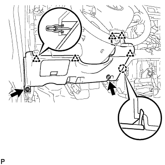
- Engage the 5 clips and claw and install the lower instrument panel finish panel.
Install the 2 <F> bolts.
| 3.
INSTALL HOOD LOCK CONTROL LEVER SUB-ASSEMBLY
|
|
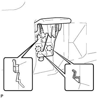
- Engage the 3 claws and install the hood lock control lever.
| 4.
INSTALL INSTRUMENT PANEL REGISTER ASSEMBLY
|
|
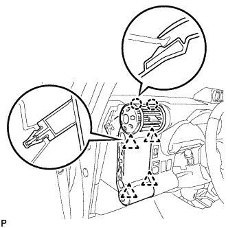
- Engage the 4 clips and 2 claws and install the instrument panel register.
| 5.
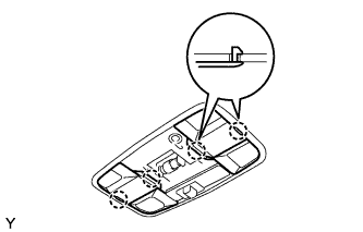
INSTALL PERSONAL LIGHT ASSEMBLY |
|
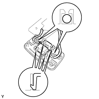
Connect the connector.
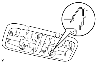
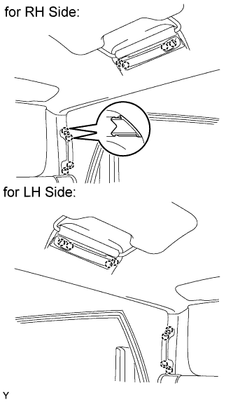
Engage the 4 claws and install the personal light.
| 6.
INSTALL NO. 1 PERSONAL LIGHT LENS |
|
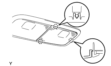
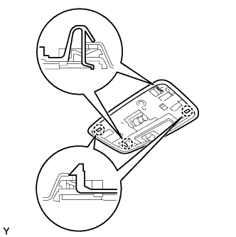
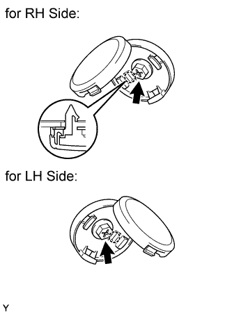
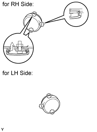
Engage the 3 claws and install the No. 1 personal light lens.
| 7.
INSTALL NO. 2 PERSONAL LIGHT LENS |
|
- HINT:
- Perform the same procedure as for the RH side.
| 8.
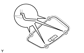
INSTALL ROOM LIGHT ASSEMBLY |
|
- HINT:
- The procedure described below is for the front side. Use the same procedure for both the front and rear sides, unless otherwise specified.
- for Front Side:
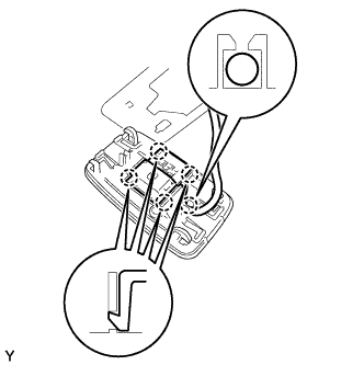
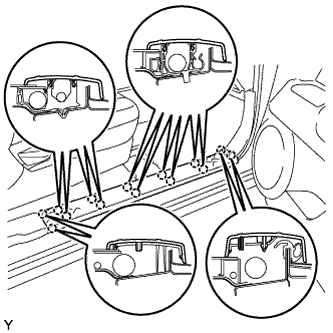
Engage the 4 claws and install the room light switch base.
Insert the 2 wire harnesses into the 2 claws of the room light.
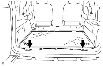
- for Rear Side:
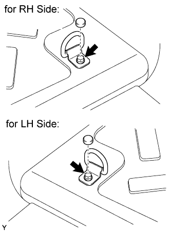
Engage the 4 claws and install the room light switch base.
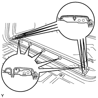
Insert the wire harness into the claw of the room light.
- Engage the 4 claws and install the room light.
- Engage the 4 claws and install the 2 covers.
- Engage the 4 claws and install the room light lens.
| 9.
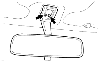
INSTALL INNER REAR VIEW MIRROR ASSEMBLY
|
|
Install the inner rear view mirror with the 2 screws.
| 10.
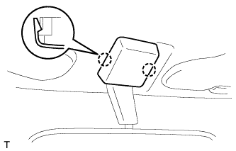
INSTALL INNER REAR VIEW MIRROR STAY HOLDER COVER
|
|
Engage the 2 claws and install the inner rear view mirror stay holder cover.
| 11.
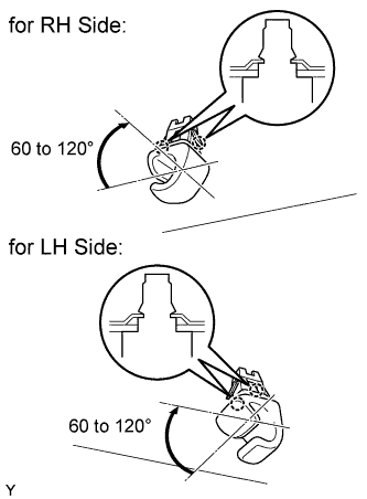
INSTALL VISOR HOLDER |
|
- HINT:
- Use the same procedure for both sides.
Engage the 2 claws by turning the visor holder clockwise between 60 to 120° and install the visor holder.
| 12.
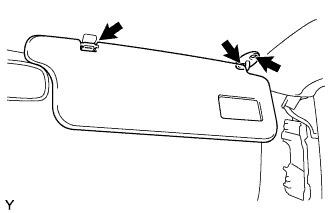
INSTALL VISOR ASSEMBLY RH |
|
- Install the visor with the 2 screws.
Install the visor support shaft into the visor holder.
| 13.
INSTALL VISOR ASSEMBLY LH |
|
- HINT:
- Use the same procedure as for the RH side.
| 14.
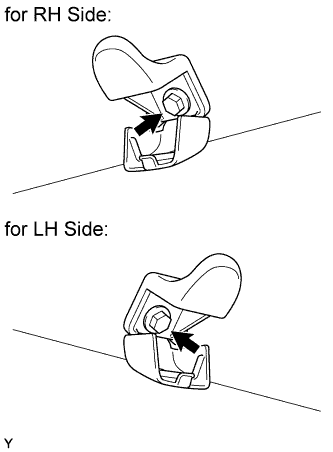
INSTALL COAT HOOK |
|
- HINT:
- Use the same procedure for both sides.
Install the coat hook with the bolt.
-
Torque:
- 8.0 N*m{
82 kgf*cm
, 71 in.*lbf
}
- Engage the claw and close the cover.
| 15.
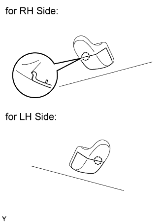
INSTALL ROOF HEADLINING HOLE PLUG |
|
- HINT:
- Use the same procedure for both sides.
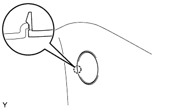
Engage the claw and install the roof headlining hole plug.
Tighten the bolt.
-
Torque:
- 5.5 N*m{
56 kgf*cm
, 49 in.*lbf
}
- Engage the 3 claws and close the cover.
| 16.
INSTALL ROOF SIDE INNER GARNISH RH |
|
- Pass the rear seat outer belt through the slit in the roof side inner garnish.
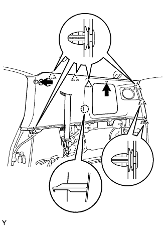
Engage the 7 clips and the claw and install the roof side inner garnish.
Tighten the bolt.
-
Torque:
- 5.5 N*m{
82 kgf*cm
, 71 in.*lbf
}
Install the clip.
- Engage the claw and close the cover.
| 17.
INSTALL ROOF SIDE INNER GARNISH LH |
|
- HINT:
- Use the same procedure as for the RH side.
| 18.
INSTALL DECK TRIM SIDE PANEL ASSEMBLY RH |
|
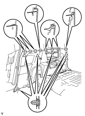
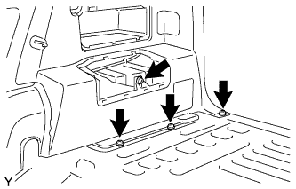
- Engage the 6 clips and the 8 claws and install the deck trim side panel.
- Tighten the 3 screws.
Tighten the bolt.
-
Torque:
- 5.5 N*m{
56 kgf*cm
, 49 in.*lbf
}
| 19.
INSTALL DECK TRIM SIDE PANEL ASSEMBLY LH |
|
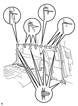
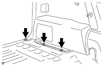
- Engage the 6 clips and the 8 claws and install the deck trim side panel.
- Tighten the 3 screws.
| 20.
INSTALL REAR SEAT OUTER BELT ASSEMBLY RH |
|
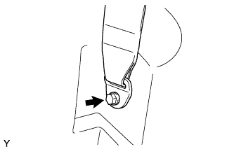
- Install the anchor plate with the bolt.
-
Torque:
- 42 N*m{
428 kgf*cm
, 31 ft.*lbf
}
Make sure that the anchor plate rotates smoothly.
| 21.
INSTALL REAR SEAT OUTER BELT ASSEMBLY LH |
|
- HINT:
- Use the same procedure as for the RH side.
| 22.
INSTALL LAP BELT OUTER ANCHOR COVER |
|
- HINT:
- Use the same procedure for both sides.
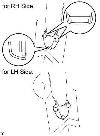
Engage the 3 claws and install the lap belt outer anchor cover.
| 23.
INSTALL AMPLIFIER BOX SPEAKER ASSEMBLY (w/ Woofer)
|
|
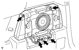
- Install the amplifier box speaker with the 4 screws.
-
Torque:
- 8.1 N*m{
85 kgf*cm
, 72 in.*lbf
}
Connect the speaker connector.
| 24.
INSTALL SPEAKER MOUNTING COVER (w/ Woofer)
|
|
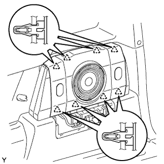
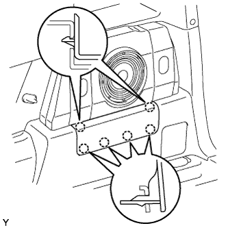
- Engage the 8 clips and install the speaker mounting cover.
| 25.
INSTALL DECK SIDE GARNISH (w/ Woofer) |
|
- Engage the 6 claws and install the deck side garnish.
| 26.
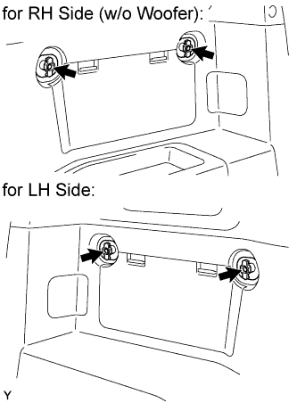
INSTALL QUARTER TRIM POCKET (w/o Woofer) |
|
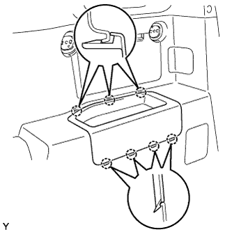
- Engage the 6 claws and install the quarter trim pocket.
| 27.
INSTALL SIDE TRIM COVER (w/o Woofer) |
|
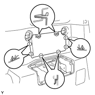
- Engage the 8 claws and install the side trim cover.
| 28.
INSTALL QUARTER TRIM POCKET TRAY (w/o Woofer) |
|
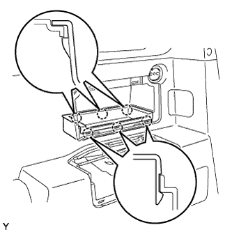
- Engage the 7 claws and install the quarter trim pocket tray.
| 29.
INSTALL PACKAGE HOLDER NET HOOK |
|
- HINT:
- Use the same procedure to install all the package holder net hooks.
Install the package holder net hook with the bolt.
-
Torque:
- 8.1 N*m{
83 kgf*cm
, 72 in.*lbf
}
| 30.
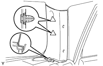
INSTALL FRONT PILLAR GARNISH RH |
|
- Engage the claw and the 2 clips and install the front pillar garnish.
| 31.
INSTALL FRONT PILLAR GARNISH LH |
|
- HINT:
- Use the same procedure as for the RH side.
| 32.
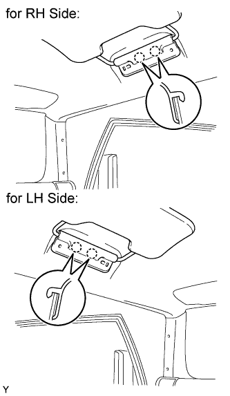
INSTALL VISOR SUB-ASSEMBLY RH |
|
Engage the 2 claws and install the visor sub-assembly.
| 33.
INSTALL VISOR SUB-ASSEMBLY LH |
|
- HINT:
- Use the same procedure as for the RH side.
| 34.
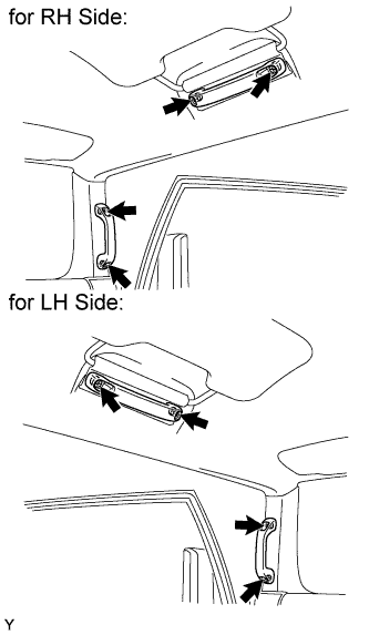
INSTALL ASSIST GRIP ASSEMBLY |
|
- HINT:
- Use the same procedure to install all the assist grips.
Install the assist grip with the 2 bolts.
-
Torque:
- 8.0 N*m{
82 kgf*cm
, 71 in.*lbf
}
| 35.
INSTALL ASSIST GRIP PLUG |
|
- HINT:
- Use the same procedure to install all the assist grip plugs.
Engage the 2 claws and install the assist grip plug.
| 36.
INSTALL FRONT DOOR OPENING TRIM WEATHERSTRIP RH |
|
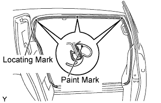
- Align the locating marks with the paint marks first, and install the front door opening trim weatherstrip, as shown in the illustration.
- Paint mark:
Area
|
Color
|
RH side
|
White
|
LH side
|
Red
|
| 37.
INSTALL FRONT DOOR OPENING TRIM WEATHERSTRIP LH |
|
- HINT:
- Use the same procedure as for the RH side.
| 38.
INSTALL ROOF SIDE RAIL GARNISH RH |
|
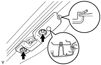
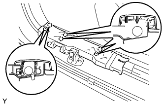
- Engage the 2 claws and install the roof side rail garnish.
Tighten the 2 bolts.
| 39.
INSTALL ROOF SIDE RAIL GARNISH LH |
|
- HINT:
- Use the same procedure as for the RH side.
| 40.
INSTALL ROOF SIDE INNER GARNISH COVER RH |
|
- HINT:
- Use the same procedure for both sides.
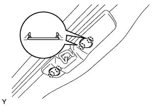
Engage the 2 claws and install the roof side inner garnish cover.
| 41.
INSTALL ROOF SIDE INNER GARNISH COVER LH |
|
- HINT:
- Use the same procedure as for the RH side.
| 42.
INSTALL COWL SIDE TRIM BOARD RH |
|
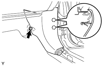
- Engage the 2 claws and install the cowl side trim board.
Install the clip.
| 43.
INSTALL COWL SIDE TRIM BOARD LH |
|
- HINT:
- Use the same procedure as for the RH side.
| 44.
INSTALL FOOTREST CLIP
|
|
- HINT:
- Use the same procedure for both sides.
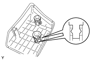
Engage the 2 claws and install the footrest clip.
| 45.
INSTALL FRONT FLOOR FOOTREST
|
|
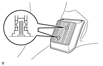
- Engage the 2 studs and install the front floor footrest.
| 46.
INSTALL ACCESS DOOR SCUFF PLATE RH |
|
- Engage the 6 claws and install the access door scuff plate.
| 47.
INSTALL ACCESS DOOR SCUFF PLATE LH |
|
- HINT:
- Use the same procedure as for the RH side.
| 48.
INSTALL FRONT DOOR SCUFF PLATE RH |
|
- Engage the 14 claws and install the door scuff plate.
| 49.
INSTALL FRONT DOOR SCUFF PLATE LH |
|
- HINT:
- Use the same procedure as for the RH side.
| 50.
INSTALL REAR FLOOR MAT ASSEMBLY |
|
- Install the rear floor mat with the 2 clips.
| 51.
INSTALL LUGGAGE HOLD BELT STRIKER ASSEMBLY |
|
- HINT:
- Use the same procedure for both sides.
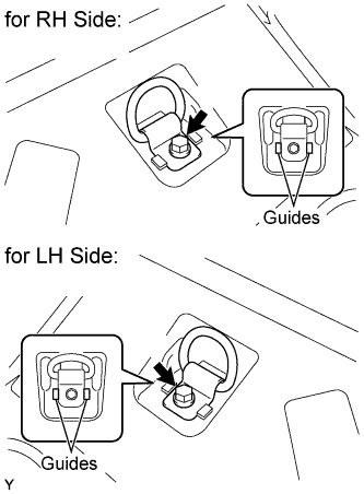
Install the luggage hold belt striker with the bolt.
-
Torque:
- 18 N*m{
184 kgf*cm
, 13 ft.*lbf
}
Install the cap.
| 52.
INSTALL REAR FLOOR MAT SUPPORT PLATE |
|
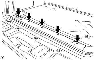
- Engage the 11 claws and install the rear floor mat support plate.
- Tighten the 5 screws.
| 53.
INSTALL REAR FLOOR BOARD |
|
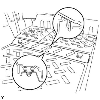
- Engage the clip and claw and install the rear floor board.
- Install the luggage hold belt striker with the bolt.
-
Torque:
- 18 N*m{
184 kgf*cm
, 13 ft.*lbf
}
- HINT:
- Use the same procedure for both sides.
| 54.
INSTALL REAR SEATBACK ASSEMBLY RH
|
|
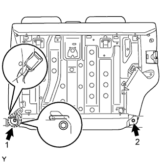
- Engage the hook and temporarily install the rear seatback with the 2 bolts.
Tighten the 2 bolts in the sequence shown in the illustration.
-
Torque:
- 37 N*m{
375 kgf*cm
, 27 ft.*lbf
}
Pull up the rear seatback.
- Install the rear seat inner belt into the rear seatback holder.
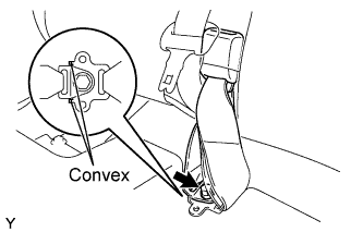
Install the anchor plate of the rear center seat outer belt with the bolt.
-
Torque:
- 42 N*m{
428 kgf*cm
, 31 ft.*lbf
}
- NOTICE:
- Do not place the anchor plate over the convex area of the rear seat inner belt.
| 55.
INSTALL REAR SEATBACK BOARD CARPET ASSEMBLY RH
|
|
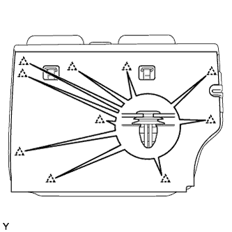
- Pull the rear seatback lock release button and tilt the rear seatback forward.
Engage the 10 clips and install the rear seatback board carpet.
Pull up the rear seatback.
| 56.
INSTALL REAR SEATBACK ASSEMBLY LH
|
|
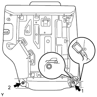
- Engage the hook and temporarily install the rear seatback with the 2 bolts.
Tighten the 2 bolts in the sequence shown in the illustration.
-
Torque:
- 37 N*m{
375 kgf*cm
, 27 ft.*lbf
}
Install the rear center seat inner belt into the rear seatback holder.
| 57.
INSTALL REAR SEATBACK BOARD CARPET ASSEMBLY LH
|
|
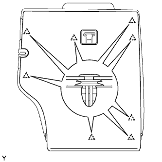
- Engage the 8 clips and install the rear seatback board carpet.
Pull up the rear seatback.
| 58.
CONNECT CABLE TO NEGATIVE BATTERY TERMINAL |
|
-
Torque:
- 3.9 N*m{
40 kgf*cm
, 35 in.*lbf
}