REASSEMBLY
Removal / installation · Vehicles built from Aug 2012
Versions by build date: Jul 2007 – Oct 2010 Nov 2010 – Jul 2012 from Aug 2012
| 1.
INSTALL REAR BUMPER EXTENSION MOUNTING BRACKET LH |
 |
Clean the attachment surface.
Using an infrared light, heat the adhesive remaining on the rear bumper cover.
- Heating Temperature:
Item
|
Temperature
|
Rear Bumper Cover
|
40 to 60°C (104 to 140°F)
|
- CAUTION:
- Do not burn yourself on the hot rear bumper cover or with the infrared light.
- NOTICE:
- Do not heat the rear bumper cover excessively.
Using a piece of cloth, rub the remaining adhesive off the rear bumper cover.
Using a non-residue solvent, clean the attachment surface.
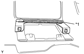
Remove the release paper from the rear bumper extension mounting bracket.
- Install the rear bumper extension mounting bracket as shown in the illustration.
Text in Illustration
*1
|
Double-sided Tape
|
- NOTICE:
- Thoroughly press the rear bumper extension mounting bracket to ensure that it adheres.
| 2.
INSTALL REAR BUMPER EXTENSION MOUNTING BRACKET RH |
|
- HINT:
- Use the same procedure as for the LH side.
| 3.
INSTALL REAR BUMPER UPPER COVER LH |
|
Clean the attachment surface.
Using an infrared light, heat the adhesive remaining on the rear bumper cover.
- Heating Temperature:
Item
|
Temperature
|
Rear Bumper Cover
|
40 to 60°C (104 to 140°F)
|
- CAUTION:
- Do not burn yourself on the hot rear bumper cover or with the infrared light.
- NOTICE:
- Do not heat the rear bumper cover excessively.
Using a piece of cloth, rub the remaining adhesive off the rear bumper cover.
Using a non-residue solvent, clean the attachment surface.
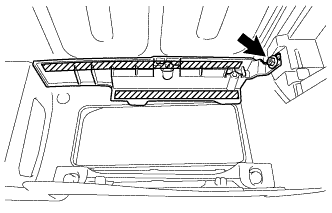
Remove the release paper from the rear bumper upper cover.
- Install the rear bumper upper cover as shown in the illustration.
Text in Illustration
*1
|
Double-sided Tape
|
- NOTICE:
- Thoroughly press the rear bumper upper cover to ensure that it adheres.
| 4.
INSTALL REAR BUMPER UPPER COVER RH |
|
- HINT:
- Use the same procedure as for the LH side.
| 5.
INSTALL REAR BUMPER PAD LH |
|
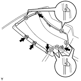
- Engage the 5 claws and install the rear bumper pad.
Install the 5 retainers.
| 6.
INSTALL REAR BUMPER PAD RH |
|
- HINT:
- Use the same procedure as for the LH side.
| 7.
INSTALL ULTRASONIC SENSOR
|
|
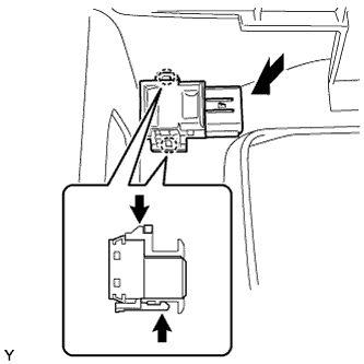
- Engage the 2 claws and install the ultrasonic sensor.
Connect the sensor connector.
| 8.
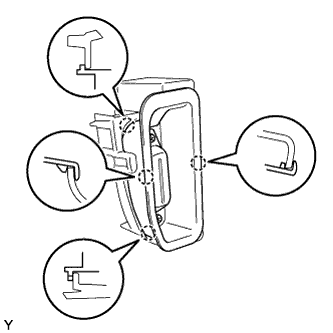
INSTALL REAR BUMPER EXTENSION MOULDING LH |
|
- Engage the 4 claws and install the rear bumper extension moulding.
| 9.
INSTALL REAR BUMPER EXTENSION MOULDING RH |
|
- HINT:
- Use the same procedure as for the LH side.
| 10.
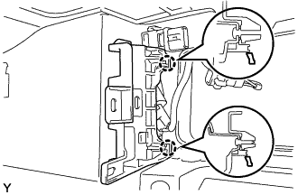
INSTALL LICENSE PLATE BRACKET HANGER ASSEMBLY (for LH Side) |
|
- Engage the 2 claws and install the license plate bracket hanger assembly.
- NOTICE:
- Be careful when engaging the claws because they are easily broken.
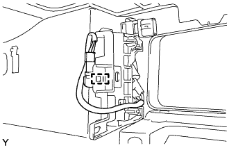
- Engage the wire harness clamp and install the wire harness.
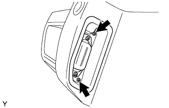
- Install the 2 screws.
| 11.
INSTALL LICENSE PLATE BRACKET HANGER ASSEMBLY (for RH Side) |
|
- HINT:
- Use the same procedure as for the LH side.
| 12.
INSTALL REAR FOG LIGHT ASSEMBLY LH
|
|
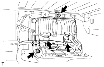
Install the rear fog light with the 2 screws.
Connect the 2 connectors and wire harness clamp.
| 13.
INSTALL REAR FOG LIGHT ASSEMBLY RH
|
|
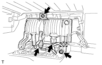
Install the rear fog light with the 2 screws.
Connect the 2 connectors and wire harness clamp.
| 14.
INSTALL REAR BUMPER SIDE RETAINER RH
|
|
Install the rear fog light with the 2 screws.
Connect the 2 connectors and wire harness clamp.
| 15.
INSTALL REAR BUMPER SIDE RETAINER LH |
|
- HINT:
- Use the same procedure as for the RH side.
| 16.
INSTALL REAR BUMPER PLATE LH |
|
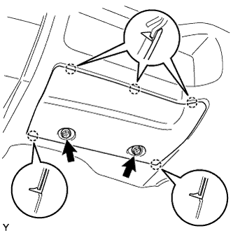
Engage the 5 claws and install the rear bumper plate.
Install the 2 screws.
| 17.
INSTALL REAR BUMPER PLATE RH |
|
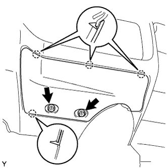
Engage the 4 claws and install the rear bumper plate.
Install the 2 screws.
| 18.
INSTALL NO. 8 FLOOR WIRE |
|
Engage the clamps.
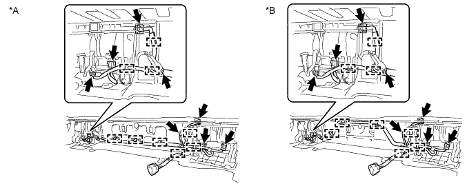

Text in Illustration
*A
|
for Type A
|
*B
|
for Type B
|
Connect the connectors.