REMOVAL
Removal / installation · Vehicles built from Aug 2014
| 1. DISCHARGE FUEL SYSTEM PRESSURE |

Connect the intelligent tester to the DLC3.
Turn the ignition switch to ON.
- NOTICE:
- Do not start the engine.
Turn the intelligent tester ON.
Enter the following menus: Powertrain / Engine and ECT / Active Test / Control the Fuel Pump Speed / ON.
Check fuel pump operation.
Check for pressure in the fuel inlet tube from the fuel line. Check that the sound of fuel flowing in the fuel tank can be heard.
If there is no sound, check the integration relay, fuel pump, ECM and wiring connector.
| 2. REMOVE CHARCOAL CANISTER ASSEMBLY |
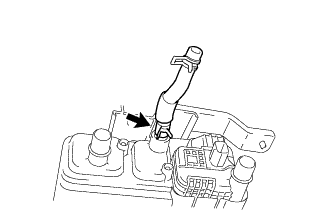
Disconnect the fuel tank vent hose from the charcoal canister assembly.
Push the fuel tank vent hose deep inside.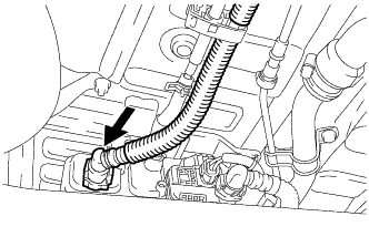

Text in Illustration 
Push
Pinch portion A, as shown in the illustration.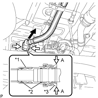
Text in Illustration *1
Nylon Tube
*2
O-ring
*3
Fuel Tank Vent Hose Retainer
Pull

Pinch
Pull out the fuel tank vent hose from the charcoal canister assembly.
- NOTICE:
- Remove any dirt and foreign objects from the fuel tank vent hose connector before performing the work.
- Do not allow any scratches or foreign objects on the parts when disconnecting, as the fuel tank vent hose connector has the O-ring that seals the pipe.
- Perform the work by hand. Do not use any tools.
- Do not forcibly bend, twist or turn the nylon tube.
- Protect the disconnected part by covering it with a vinyl bag after disconnecting the fuel tank vent hose.
- If the fuel tank vent hose connector and pipe are stuck, push and pull them to release.
- Remove any dirt and foreign objects from the fuel tank vent hose connector before performing the work.
Disconnect the No. 2 canister outlet hose sub-assembly.
Push the No. 2 canister outlet hose sub-assembly deep inside.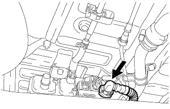
Text in Illustration
Push
Pinch portion A, as shown in the illustration.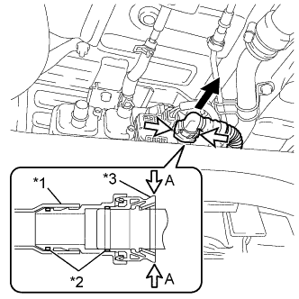
Text in Illustration *1
Nylon Tube
*2
O-ring
*3
No. 2 Canister Outlet Hose Sub-assembly Retainer
Pull
Pinch
Pull out the No. 2 canister outlet hose sub-assembly from the charcoal canister assembly.
- NOTICE:
- Remove any dirt and foreign objects from the No. 2 canister outlet hose sub-assembly connector before performing the work.
- Do not allow any scratches or foreign objects on the parts when disconnecting, as the No. 2 canister outlet hose sub-assembly connector has the O-ring that seals the pipe.
- Perform the work by hand. Do not use any tools.
- Do not forcibly bend, twist or turn the nylon tube.
- Protect the disconnected part by covering it with a vinyl bag after disconnecting the No. 2 canister outlet hose sub-assembly.
- If the No. 2 canister outlet hose sub-assembly and pipe are stuck, push and pull them to release.
- Remove any dirt and foreign objects from the No. 2 canister outlet hose sub-assembly connector before performing the work.
Disconnect the leak detection pump sub-assembly connector.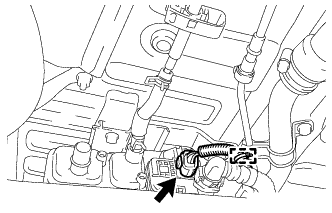
Disengage the clamp to disconnect the wire harness from the charcoal canister bracket.
Slide the hose clip and disconnect the fuel hose from the No. 1 charcoal canister tube.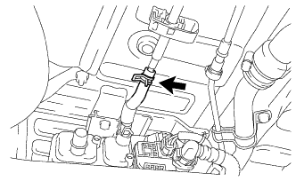
Remove the 3 bolts and charcoal canister assembly from the vehicle.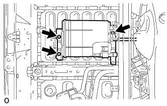
Slide the hose clip and remove the fuel hose from the charcoal canister assembly.