INSTALLATION
Removal / installation · Vehicles built from Aug 2014
Versions by build date: Jul 2007 – Jul 2009 Aug 2009 – Oct 2010 Nov 2010 – Jul 2013 Aug 2013 – Jul 2014 from Aug 2014
| 1. INSTALL RADIATOR DRAIN COCK SUB-ASSEMBLY |

Install the radiator drain cock sub-assembly to the radiator assembly.
- HINT:
- Replace the O-ring if it is damaged.
| 2. INSTALL NO. 1 RADIATOR SUPPORT BUSH |
Install the 4 No. 1 radiator support bushes, 2 No. 1 radiator supports and 2 No. 2 radiator supports to the radiator assembly.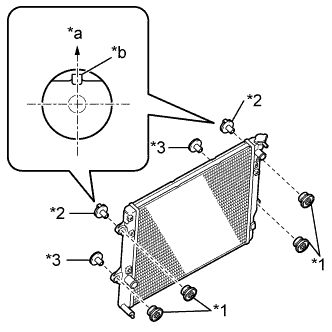

Text in Illustration *1
No. 1 Radiator Support Bush
*2
No. 1 Radiator Support
*3
No. 2 Radiator Support
*a
Top of Vehicle
*b
Claw
- HINT:
- With the claw of the No. 1 radiator support facing towards the top of the vehicle, install the No. 1 radiator support to the No. 1 radiator support bush.
| 3. INSTALL NO. 1 RADIATOR HOSE |
Connect the No. 1 radiator hose to the radiator assembly and slide the hose clip to secure it.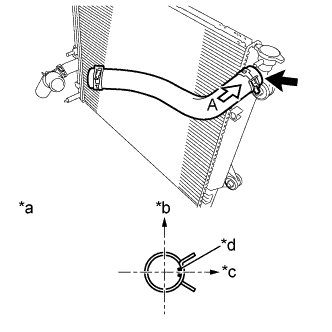
Text in Illustration *a
View A
*b
Upper Side
*c
RH Side
*d
Hose Paint Mark
- HINT:
- Perform the installation with the hose clip at the correct angle.
| 4. INSTALL NO. 2 RADIATOR HOSE |
Connect the No. 2 radiator hose to the radiator assembly and slide the hose clip to secure it.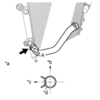
Text in Illustration *a
View A
*b
Upper Side
*c
LH Side
*d
Hose Paint Mark
- HINT:
- Perform the installation with the hose clip at the correct angle.
| 5. INSTALL RADIATOR ASSEMBLY |
Install the radiator assembly to the vehicle with the 4 bolts.
- Torque:
- 18 N*m{ 184 kgf*cm , 13 ft.*lbf }
| 6. CONNECT NO. 1 RADIATOR HOSE (w/ Secondary Air Injection System) |
Connect the No. 1 radiator hose to the water inlet housing and slide the hose clip to secure it.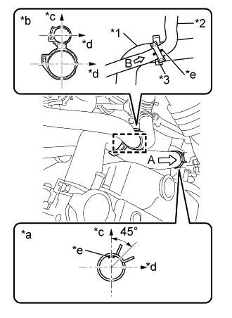
Text in Illustration *1
No. 1 Radiator Hose
*2
No. 1 Air Injection System Hose
*3
Hose Clamp
*a
View A
*b
View B
*c
Upper Side
*d
Front Side
*e
Hose Paint Mark
Install a new hose clamp to the No. 1 radiator hose and No. 1 air injection system hose at the location shown in the illustration.
- HINT:
- Perform the installation with the hose clamp at the correct angle.
| 7. CONNECT NO. 1 RADIATOR HOSE (w/o Secondary Air Injection System) |
Connect the No. 1 radiator hose to the water inlet housing and slide the hose clip to secure it.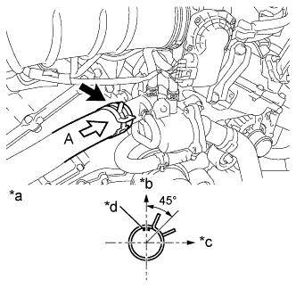
*a
View A
*b
Upper Side
*c
Front Side
*d
Hose Paint Mark
- HINT:
- Perform the installation with the hose clip at the correct angle.
| 8. CONNECT NO. 2 RADIATOR HOSE |
Connect the No. 2 radiator hose to the water inlet with thermostat and slide the hose clip to secure it.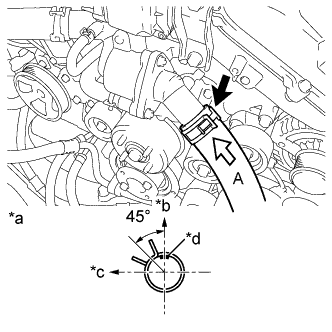
Text in Illustration *a
View A
*b
Upper Side
*c
Front Side
*d
Hose Paint Mark
- HINT:
- Perform the installation with the hose clip at the correct angle.
| 9. CONNECT OIL COOLER HOSE (for Automatic Transmission) |
Connect the 2 oil cooler hoses to the radiator assembly and slide the 2 hose clips to secure them.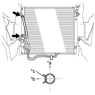
Text in Illustration *a
Upper Side
*b
LH Side
*c
Hose Paint Mark
- HINT:
- Perform the installation with the hose clip at the correct angle.
| 10. INSTALL RADIATOR GRILLE |
Engage the 5 clips and install the radiator grille.
Install the 2 screws.
- Torque:
- 3.0 N*m{ 31 kgf*cm , 27 in.*lbf }
Install the 2 clips.
| 11. INSTALL FAN SHROUD (for Automatic Transmission) |
Install the fan pulley to the engine water pump assembly.
Place the fan shroud together with the fan and fluid coupling assembly between the radiator assembly and engine.
- NOTICE:
- Be careful not to damage the radiator core.
Align the paint marks of the same color (pink to pink and black to black) on the stud bolts of the engine water pump assembly and the outer flange of the fan and fluid coupling assembly, and assemble the parts.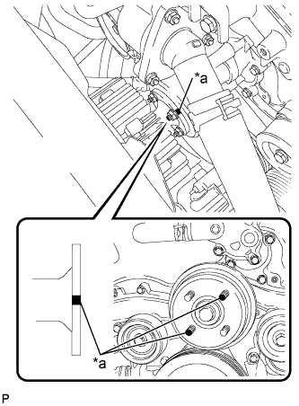
Text in Illustration *a
Paint Mark
Temporarily install the fan and fluid coupling assembly to the engine water pump assembly with the 4 nuts. Tighten the nuts as much as possible by hand.
Engage the 2 guides of the fan shroud to the radiator assembly as shown in the illustration.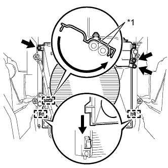
Text in Illustration *1
Oil Cooler Hose
Install the fan shroud to the radiator assembly with the 2 bolts.
- Torque:
- 5.0 N*m{ 51 kgf*cm , 44 in.*lbf }
Install the radiator reserve tank assembly to the radiator assembly with the bolt.
- Torque:
- 5.0 N*m{ 51 kgf*cm , 44 in.*lbf }
Install the 2 oil cooler hoses to the hose clamp and engage the clamp.
Set the fan and generator V belt onto every part.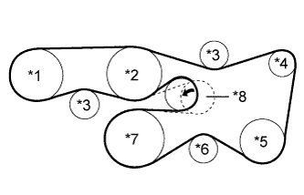
Text in Illustration *1
Vane Pump Assembly
*2
Engine Water Pump Assembly
*3
No. 2 Idler Pulley Sub-Assembly
*4
Generator Assembly
*5
Cooler Compressor Assembly
*6
No. 1 Idler Pulley Sub-Assembly
*7
Crankshaft Pulley
*8
V-ribbed Belt Tensioner Assembly
While turning the V-ribbed belt tensioner assembly counterclockwise, remove the pin.
- NOTICE:
- Make sure that the fan and generator V belt is properly set to each pulley.
Check that the belt fits properly in the ribbed grooves.
- HINT:
- Make sure to check by hand that the belt has not slipped out of the grooves on the bottom of the pulley.
Tighten the 4 nuts of the fan and fluid coupling assembly.
- Torque:
- 21 N*m{ 214 kgf*cm , 15 ft.*lbf }
Connect the radiator reserve tank hose to the radiator assembly.
| 12. INSTALL FAN SHROUD (for Manual Transmission) |
Install the fan pulley to the engine water pump assembly.
Place the fan shroud together with the fan and fluid coupling assembly between the radiator assembly and engine.
- NOTICE:
- Be careful not to damage the radiator core.
Align the paint marks of the same color (pink to pink and black to black) on the stud bolts of the engine water pump assembly and the outer flange of the fan and fluid coupling assembly, and assemble the parts.
Text in Illustration *a
Paint Mark
Temporarily install the fan and fluid coupling assembly to the engine water pump assembly with the 4 nuts. Tighten the nuts as much as possible by hand.
Engage the 2 guides of the fan shroud to the radiator assembly as shown in the illustration.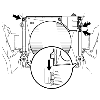
Install the fan shroud to the radiator assembly with the 2 bolts.
- Torque:
- 5.0 N*m{ 51 kgf*cm , 44 in.*lbf }
Install the radiator reserve tank assembly to the radiator assembly with the bolt.
- Torque:
- 5.0 N*m{ 51 kgf*cm , 44 in.*lbf }
Set the fan and generator V belt onto every part.
Text in Illustration *1
Vane Pump Assembly
*2
Engine Water Pump Assembly
*3
No. 2 Idler Pulley Sub-Assembly
*4
Generator Assembly
*5
Cooler Compressor Assembly
*6
No. 1 Idler Pulley Sub-Assembly
*7
Crankshaft Pulley
*8
V-ribbed Belt Tensioner Assembly
While turning the V-ribbed belt tensioner assembly counterclockwise, remove the pin.
- NOTICE:
- Make sure that the fan and generator V belt is properly set to each pulley.
Check that the belt fits properly in the ribbed grooves.
- HINT:
- Make sure to check by hand that the belt has not slipped out of the grooves on the bottom of the pulley.
Tighten the 4 nuts of the fan and fluid coupling assembly.
- Torque:
- 21 N*m{ 214 kgf*cm , 15 ft.*lbf }
Connect the radiator reserve tank hose to the radiator assembly.
| 13. INSTALL UPPER RADIATOR SUPPORT SEAL |
Engage the 7 clips to install the upper radiator support seal to the fan shroud.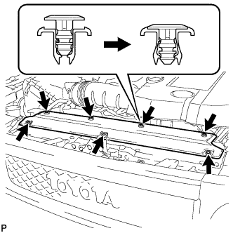
| 14. ADD ENGINE COOLANT |
Tighten the cylinder block drain cock plug.
- Torque:
- 13 N*m{ 133 kgf*cm , 10 ft.*lbf }
Tighten the radiator drain cock plug by hand.
Remove the vinyl hose from the radiator drain cock of the radiator assembly.
Add engine coolant.
- Standard Capacity:
Item
Specified Condition
for Automatic Transmission
9.8 liters (10.4 US qts, 8.6 Imp. qts)
for Manual Transmission
9.4 liters (9.9 US qts, 8.3 Imp. qts)
- NOTICE:
- Do not substitute plain water for engine coolant.
- HINT:
- TOYOTA vehicles are filled with TOYOTA SLLC at the factory. In order to avoid damage to the engine cooling system and other technical problems, only use TOYOTA SLLC or similar high quality ethylene glycol based non-silicate, non-amine, non-nitrite, non-borate engine coolant with long-life hybrid organic acid technology (engine coolant with long-life hybrid organic acid technology consists of a combination of low phosphates and organic acids).
- Press the No. 1 radiator hose and No. 2 radiator hose several times by hand, and then check the engine coolant level. If the engine coolant level is low, add engine coolant.
- TOYOTA vehicles are filled with TOYOTA SLLC at the factory. In order to avoid damage to the engine cooling system and other technical problems, only use TOYOTA SLLC or similar high quality ethylene glycol based non-silicate, non-amine, non-nitrite, non-borate engine coolant with long-life hybrid organic acid technology (engine coolant with long-life hybrid organic acid technology consists of a combination of low phosphates and organic acids).
Slowly pour engine coolant into the radiator reservoir until it reaches the Full line.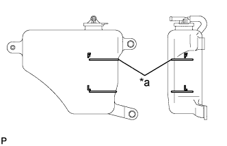
Text in Illustration *a
Full Line
Install the radiator reserve tank cap sub-assembly.
Install the radiator cap sub-assembly.*1
Start the engine and stop it immediately.*2
Allow approximately 10 seconds to pass, and then remove the radiator cap sub-assembly and check the engine coolant level. If the engine coolant level has decreased, add engine coolant.*3
Repeat steps *1, *2 and *3 until the engine coolant level does not decrease.
- HINT:
- Be sure to perform this step while the engine is cold, as air in the No. 1 radiator hose will flow into the radiator assembly if the engine is warmed up and the thermostat opens.
Install the radiator cap sub-assembly.*4
Set the air conditioning as follows.*5
Item
Condition
Fan speed
Any setting except off
Temperature
Toward WARM
Air conditioning switch
Off
Start the engine, warm it up until the thermostat opens, and then continue to run the engine for several minutes to circulate the engine coolant.*6
- CAUTION:
- Wear protective gloves. Hot areas on the parts may injure your hands.
- Be careful of the fan.
- Be careful as the engine, radiator assembly and radiator hoses are hot and can cause burns.
- Wear protective gloves. Hot areas on the parts may injure your hands.
- NOTICE:
- Immediately after starting the engine, if the radiator reservoir becomes empty, perform the following: 1) stop the engine, 2) wait until the engine coolant has cooled down, and 3) add engine coolant until the engine coolant is filled to the Full line.
- Do not start the engine when there is no engine coolant in the radiator reservoir.
- Pay attention to the needle of the engine coolant temperature receiver gauge. Make sure that the needle does not show an abnormally high temperature.
- If there is not enough engine coolant, the engine may burn out or overheat.
- Immediately after starting the engine, if the radiator reservoir becomes empty, perform the following: 1) stop the engine, 2) wait until the engine coolant has cooled down, and 3) add engine coolant until the engine coolant is filled to the Full line.
- HINT:
- Press the No. 1 radiator hose and No. 2 radiator hose several times by hand to bleed air while warming up the engine.
- The thermostat opening timing can be confirmed by pressing the No. 2 radiator hose by hand and checking when the engine coolant starts to flow inside the hose.
- Press the No. 1 radiator hose and No. 2 radiator hose several times by hand to bleed air while warming up the engine.
Stop the engine, wait until the engine coolant cools down to ambient temperature, and then remove the radiator cap sub-assembly and check the engine coolant level.*7
- CAUTION:
- Do not remove the radiator cap sub-assembly while the engine and radiator assembly are still hot. Pressurized, hot engine coolant and steam may be released and cause serious burns.
If the engine coolant level has decreased, add engine coolant and warm up the engine until the thermostat opens.*8
If the engine coolant level has not decreased, check that the engine coolant level in the radiator reservoir is at the Full line.
If the engine coolant level is below the Full line, repeat steps *4 through *8.
If the engine coolant level is above the Full line, drain engine coolant until the engine coolant level reaches the Full line.Text in Illustration *a
Full Line
Install the service hole cover to the engine under cover.
| 15. INSPECT FOR ENGINE COOLANT LEAK |
- CAUTION:
- To avoid being burned, do not remove the radiator reservoir cap while the engine and radiator are still hot. Thermal expansion may cause hot engine coolant and steam to blow out from the radiator.
Fill the radiator with engine coolant, and then attach a radiator cap tester.
Warm up the engine.
Using the radiator cap tester, increase the pressure inside the radiator to 123 kPa (1.3 kgf/cm2, 18 psi), and then check that the pressure does not drop.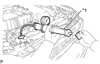
If the pressure drops, check the hoses, radiator and water pump for leakage. If there are no signs or traces of external engine coolant leakage, check the heater core, cylinder block and head.Text in Illustration *1
Radiator Cap Tester
| 16. INSTALL NO. 1 ENGINE UNDER COVER SUB-ASSEMBLY |
Hook the engine under cover to the frame.
Install the 4 bolts.
- Torque:
- 29 N*m{ 296 kgf*cm , 21 ft.*lbf }
| 17. INSTALL V-BANK COVER |
Engage the 2 hooks to install the V-bank cover to the No. 1 V-bank cover bracket.
Align the 2 cushions of the V-bank cover with the 2 pins and press down on the V-bank cover to engage the 2 cushions to the 2 pins.