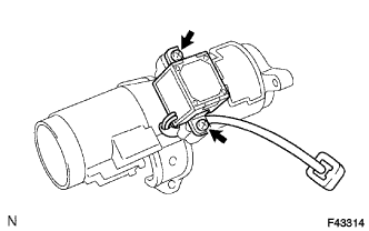
DISASSEMBLY
Removal / installation · Vehicles built from Jul 2007
| 1. REMOVE STEERING INTERMEDIATE SHAFT ASSEMBLY |

Remove the bolt and separate the steering shaft thrust stopper from the steering intermediate shaft assembly.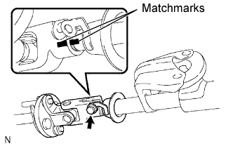

Mark matchmarks on the steering column assembly and steering intermediate shaft.
Pull out the intermediate shaft assembly and steering shaft thrust stopper from the steering column assembly.
| 2. REMOVE STEERING COLUMN UPPER CLAMP |
Using a 3 mm (0.12 in.) pin punch, mark the center of the 2 tapered-head bolts.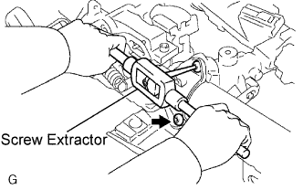
Using a 3 to 4 mm (0.12 - 0.16 in.) drill, drill into the 2 bolts.
Using a screw extractor, remove the 2 tapered-head bolts, steering column bracket assembly upper and steering column upper clamp.
| 3. REMOVE STEERING MAIN SHAFT ASSEMBLY |
Using SST, remove the 2 tension springs.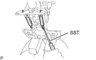
- SST
- 09921-00010
Remove the 2 bolts and steering column protector.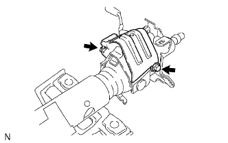
Using SST, remove the tension spring.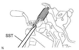
- SST
- 09921-00010
Remove the 2 bolts and the turn signal bracket.
Using a 6 mm hexagon wrench, remove the 2 tilt steering bolts.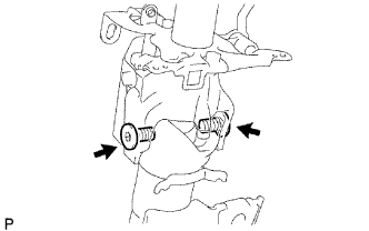
Pull out the main shaft with the steering column tube sub-assembly upper from the column tube.
Bend the joint of the main shaft at right angles, and leaving the cross ball in the No. 2 main shaft sub-assembly, divide the main shaft into the No. 1 main shaft with the steering column tube sub-assembly upper and the No. 2 main shaft sub-assembly.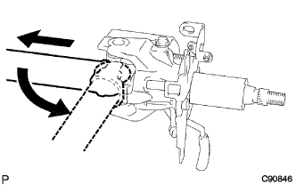
Secure the No. 1 main shaft with the steering column tube sub-assembly upper and SST in a vise.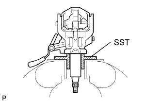
- SST
- 09316-60011
(09316-00051)
Using SST, compress the spring of the steering column tube sub-assembly upper.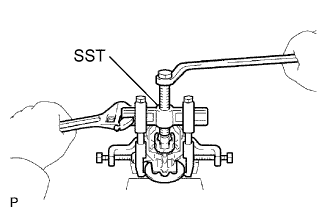
- SST
- 09950-40011
(09951-04010, 09952-04010, 09953-04020, 09954-04010, 09955-04061, 09958-04011)
- NOTICE:
- Do not overtighten SST.
Using a snap ring expander, remove the snap ring and No. 1 main shaft.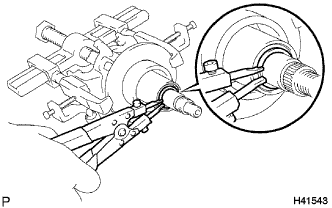
Remove the compression spring, bearing thrust collar and bearing from the No. 1 main shaft.
| 4. REMOVE TRANSPONDER KEY AMPLIFIER |
Disengage the 2 claws and slide the transponder key amplifier in the direction shown in the illustration, to detach it from the steering column upper with switch bracket assembly.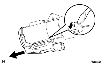
| 5. REMOVE IGNITION SWITCH LOCK CYLINDER ASSEMBLY |
Turn the ignition switch lock cylinder assembly in the ACC position.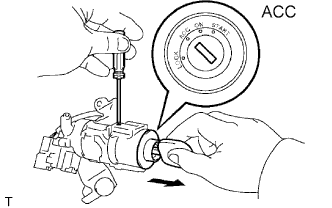
Push down the stop pin with a screwdriver and pull out the ignition switch lock cylinder assembly.
| 6. REMOVE UN-LOCK WARNING SWITCH ASSEMBLY |
Disconnect the un-lock warning switch assembly connector from the ignition or starter switch assembly.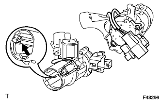
Remove the un-lock warning switch assembly toward the rear of the vehicle by pushing up the center part.
| 7. REMOVE IGNITION OR STARTER SWITCH ASSEMBLY |
Remove the 2 screws and ignition or starter switch assembly from the steering column bracket assembly upper.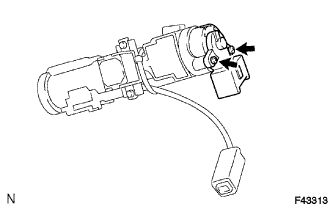
| 8. REMOVE KEY INTER LOCK SOLENOID (for Automatic Transmission) |
Remove the 2 screws and key inter lock solenoid from the steering column bracket assembly upper.