REMOVAL
Removal / installation · Vehicles built Aug 2009 – Oct 2010
Versions by build date: Jul 2007 – Jul 2009 Aug 2009 – Oct 2010 Nov 2010 – Jul 2014 from Aug 2014
| 1.
REMOVE ENGINE ASSEMBLY |
 |
Remove the engine assembly (Click here).
| 2.
REMOVE IGNITION COIL ASSEMBLY
|
|
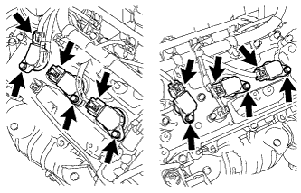
- Disconnect the 6 ignition coil connectors.
Remove the 6 bolts and 6 ignition coils.
| 3.
REMOVE ENGINE OIL LEVEL DIPSTICK GUIDE |
|
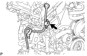
Remove the dipstick.
Remove the bolt and dipstick guide.
Remove the O-ring from the dipstick guide.
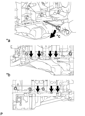
| 4.
REMOVE WATER BY-PASS PIPE SUB-ASSEMBLY (w/ Oil Cooler) |
|
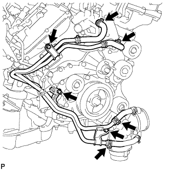
Disconnect the 4 hoses.
Remove the 3 bolts and water by-pass pipe.
| 5.
REMOVE WATER INLET HOUSING |
|
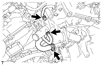
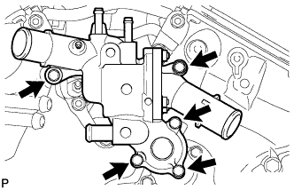
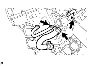
Disconnect the 3 water by-pass hoses.
- Remove the 5 bolts and water inlet housing.
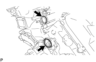
- Remove the O-ring and gasket from the water outlet pipe and water pump.
- Remove the 3 water by-pass hoses.
| 6.
REMOVE NO. 1 IDLER PULLEY SUB-ASSEMBLY |
|
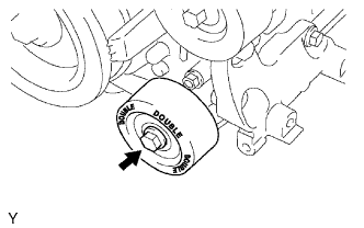
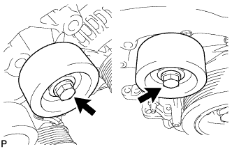
Remove the bolt and No. 1 idler pulley.
| 7.
REMOVE NO. 2 IDLER PULLEY SUB-ASSEMBLY |
|
for Cover Separate Type:
Remove the 2 bolts, 2 idler pulley cover plates, 2 No. 2 idler pulleys, and 2 No. 2 idler pulley cover plates.
for Cover Integrated Type:
Remove the 2 bolts and 2 No. 2 idler pulleys.
| 8.
REMOVE V-RIBBED BELT TENSIONER ASSEMBLY |
|
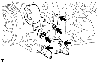
Remove the 5 bolts and V-ribbed belt tensioner.
| 9.
REMOVE OIL FILTER BRACKET |
|
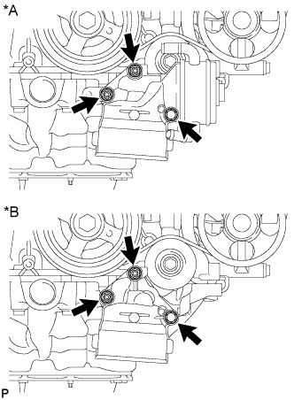
Remove the 2 nuts, bolt, oil filter bracket and gasket.
Text in Illustration
*A
|
w/ Oil Cooler:
|
*B
|
w/o Oil Cooler:
|
| 10.
REMOVE CRANKSHAFT PULLEY |
|
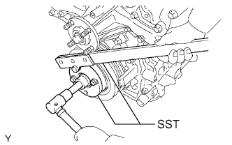
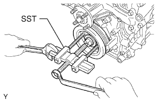
Using SST, hold the crankshaft pulley and loosen the pulley bolt. Further loosen the bolt until 2 or 3 threads are screwed into the crankshaft.
- SST
- 09213-54015
(91651-60855)
09330-00021
- Using the pulley set bolt and SST, remove the crankshaft pulley and pulley bolt.
- SST
- 09950-50013
(09951-05010, 09952-05010, 09953-05020, 09954-05031)
| 11.
REMOVE NO. 1 OIL PIPE |
|
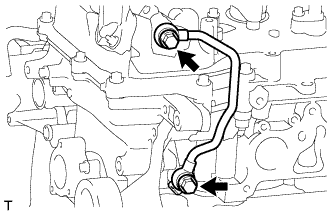
Remove the 2 oil pipe unions, gaskets and No. 1 oil pipe.
Remove the oil control valve filter LH and gaskets.
- NOTICE:
- Do not touch the mesh when removing the oil control valve filter.
| 12.
REMOVE NO. 2 OIL PIPE |
|
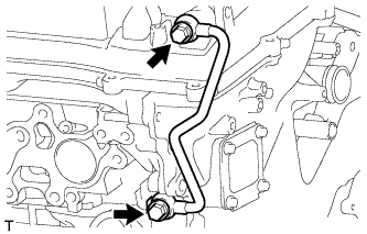
Remove the 2 oil pipe unions, gaskets and No. 2 oil pipe.
Remove the oil control valve filter RH and gaskets.
- NOTICE:
- Do not touch the mesh when removing the oil control valve filter.
| 13.
REMOVE REAR CYLINDER HEAD COVER
|
|
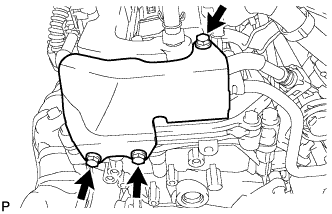
- Remove the 3 bolts and cover.
| 14.
DISCONNECT FUEL PIPE SUB-ASSEMBLY |
|
Remove the 2 bolts and disconnect the fuel pipe.
| 15.
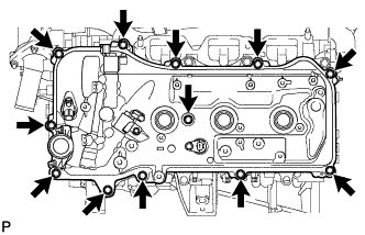
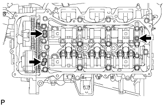
REMOVE CYLINDER HEAD COVER SUB-ASSEMBLY LH |
|
Remove the 12 bolts, seal washer, cylinder head cover and gasket.
- HINT:
- Make sure the removed parts are returned to the same places they were removed from.
- Remove the 3 gaskets.
| 16.
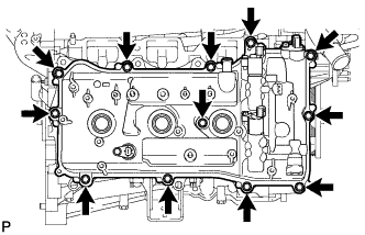
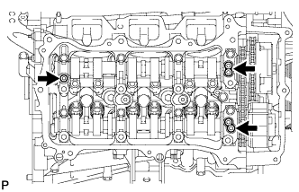
REMOVE CYLINDER HEAD COVER SUB-ASSEMBLY |
|
Remove the 12 bolts, seal washer, cylinder head cover and gasket.
- HINT:
- Make sure the removed parts are returned to the same places they were removed from.
- Remove the 3 gaskets.
| 17.
REMOVE NO. 2 OIL PAN SUB-ASSEMBLY |
|
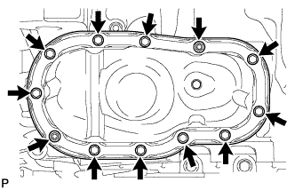
Remove the 10 bolts and 2 nuts.
- HINT:
- Make sure the removed parts are returned to the same places they were removed from.
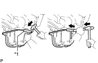
- Insert the blade of an oil pan seal cutter between the oil pans. Cut through the applied sealer and remove the No. 2 oil pan.
Text in Illustration
*1
|
Oil Pan Seal Cutter
|
- NOTICE:
- Be careful not to damage the contact surfaces of the oil pans.
| 18.
REMOVE OIL STRAINER SUB-ASSEMBLY |
|
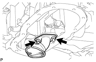
Remove the 2 nuts, oil strainer and gasket.
| 19.
REMOVE OIL PAN SUB-ASSEMBLY |
|
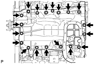
Remove the 17 bolts and 2 nuts.
- HINT:
- Make sure the removed parts are returned to the same places they were removed from.
- Using a screwdriver, remove the oil pan by prying between the oil pan and cylinder block as shown in the illustration.
Text in Illustration
*a
|
LH Side:
|
*b
|
RH Side:
|
*c
|
Pry
|
- NOTICE:
- Be careful not to damage the contact surfaces of the cylinder block or oil pan.
- HINT:
- Tape the screwdriver tip before use.
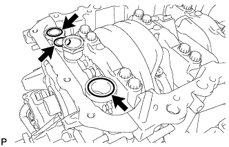
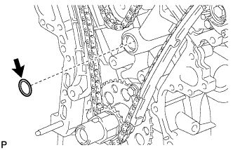
- Remove the 3 O-rings from the timing chain cover.
| 20.
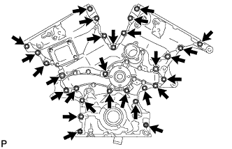
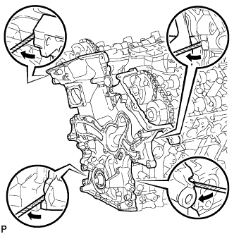
REMOVE TIMING CHAIN COVER SUB-ASSEMBLY |
|
Remove the 26 bolts and the 2 nuts.
- Remove the timing chain cover by prying between the timing chain cover and cylinder head or cylinder block with a screwdriver.
- HINT:
- Tape the screwdriver tip before use.
- NOTICE:
- Be careful not to damage the contact surfaces of the timing chain cover, cylinder block or cylinder head.
- Remove the oil pump gasket from the cylinder block.
| 21.
REMOVE FRONT CRANKSHAFT OIL SEAL |
|
Using a screwdriver and wooden block, pry out the oil seal.
- HINT:
- Tape the screwdriver tip before use.
- NOTICE:
- Do not damage the surface of the oil seal press fit hole.