Enter the following menus: Powertrain / Engine and ECT / Active Test / Control the Fuel Pump Speed / ON.
Check fuel pump operation.
Check for pressure in the fuel inlet tube from the fuel line. Check that the sound of fuel flowing in the fuel tank can be heard. If there is no sound, check the integration relay, fuel pump, ECM and wiring connector.
2.
REMOVE NO. 1 ENGINE UNDER COVER SUB-ASSEMBLY
3.
DRAIN ENGINE COOLANT
CAUTION:
Do not remove the radiator cap sub-assembly while the engine and radiator assembly are still hot. Pressurized, hot engine coolant and steam may be released and cause serious burns.
Remove the service hole cover from the engine under cover.
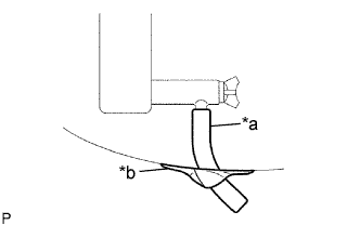
Install a vinyl hose to the radiator drain cock on the radiator assembly side.
Text in Illustration
*a
Vinyl Hose
*b
Tape
Fix the vinyl hose with tape.
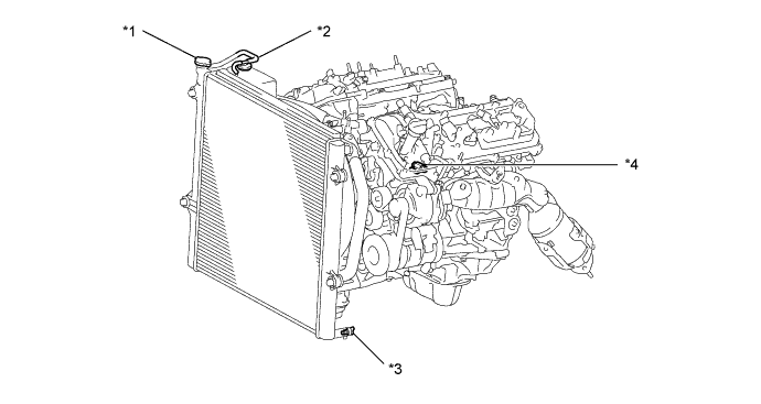
Text in Illustration
*1
Radiator Cap Sub-assembly
*2
Radiator Reserve Tank Cap Sub-assembly
*3
Radiator Drain Cock Plug
*4
Cylinder Block Drain Cock Plug
Loosen the radiator drain cock plug.
Remove the radiator cap sub-assembly and drain the engine coolant.
HINT:
Collect the engine coolant in a container and dispose of it according to the regulations in your area.
Loosen the cylinder block drain cock plug and drain the engine coolant from the engine.
NOTICE:
If engine coolant is not drained from the radiator drain cock plug, cylinder block drain cock plug and radiator reservoir, clogging in the radiator assembly or engine coolant leakage from the seal of water pump may result.
4.
REMOVE V-BANK COVER
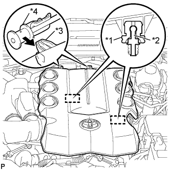
Raise the front of the V-bank cover to disengage the 2 cushions of the V-bank cover from the 2 pins.
Text in Illustration
*1
Cushion
*2
Pin
*3
Hook
*4
No. 1 V-bank Cover Bracket
Disengage the 2 hooks to remove the V-bank cover from the No. 1 V-bank cover bracket.
5.
REMOVE AIR CLEANER HOSE ASSEMBLY
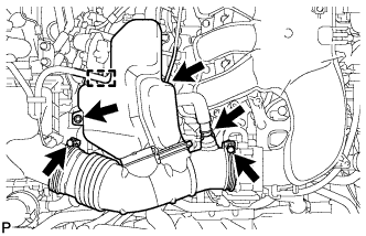
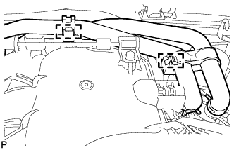
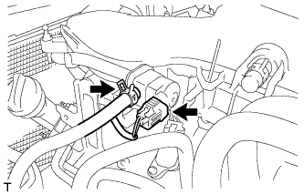
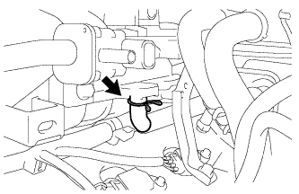
Slide the hose clip and disconnect the ventilation hose from the air cleaner hose assembly.
Disconnect the vacuum hose from the air cleaner hose assembly.
Disengage the clamp to separate the wire harness from the air cleaner hose assembly.
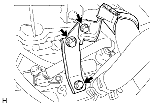
Remove the bolt to separate the air cleaner hose assembly from the resonator bracket.
Loosen the 2 hose clamps and remove the air cleaner hose assembly from air cleaner cap sub-assembly and intake air surge tank.
6.
DISCONNECT NO. 1 AIR INJECTION SYSTEM HOSE (w/ Secondary Air Injection System)
Slide the hose clip and disconnect the No. 1 air injection system hose from the air tube assembly.
7.
REMOVE AIR TUBE ASSEMBLY (w/ Secondary Air Injection System)
Remove the bolt to separate the air tube assembly from the timing chain cover sub-assembly.
Slide the hose clip and disconnect the air tube assembly from the No. 1 emission control valve set.
Remove the 2 bolts to separate the air tube assembly from the timing chain cover sub-assembly and No. 1 surge tank stay.
Slide the hose clip and disconnect the air tube assembly from the No. 2 emission control valve set.
8.
REMOVE INTAKE AIR SURGE TANK
Disconnect the throttle body with motor assembly connector.
Slide the 2 hose clips and disconnect the No. 4 water by-pass hose and No. 5 water by-pass hose from the water inlet housing.
Disengage the 2 clamps to separate the heater water hose from the intake air surge tank.
Disconnect the purge VSV connector.
Slide the hose clip and disconnect the No. 1 fuel vapor feed hose from the purge VSV.
Slide the hose clip and disconnect the No. 1 ventilation hose from the intake air surge tank.
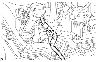
Remove the bolt to separate the wire harness clamp bracket from the No. 2 surge tank stay. (for RHD)
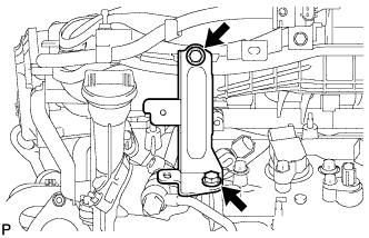
Remove the 2 bolts and No. 2 surge tank stay from the intake air surge tank.
Disengage the clamp to separate the wire harness from the No. 1 surge tank stay.
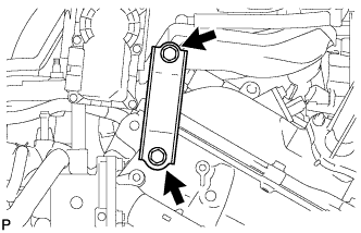
Remove the 2 bolts and No. 1 surge tank stay from the intake air surge tank.
Remove the 2 bolts and throttle body bracket from the intake air surge tank.
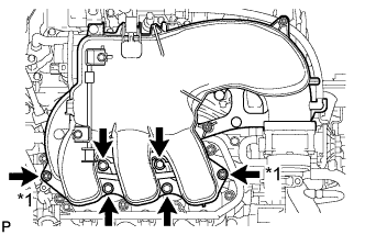
Using an 8 mm socket hexagon wrench, remove the 4 bolts, 2 nuts and intake air surge tank from the intake manifold.
Text in Illustration
*1
Nut
Remove the air surge tank to intake manifold gasket from the intake air surge tank.
9.
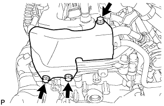
REMOVE REAR CYLINDER HEAD COVER
Remove the 3 bolts and cover.
10.
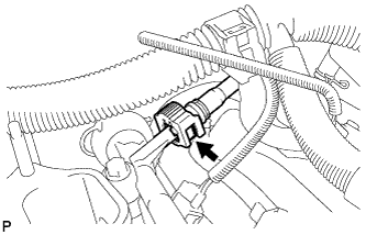
DISCONNECT NO. 1 FUEL PIPE SUB-ASSEMBLY
Disconnect the No. 1 fuel pipe sub-assembly (Click here).
NOTICE:
Check for dirt or other foreign matter on the parts to be disconnected and clean them if necessary.
The fuel tube connector seals with an O-ring. Ensure that there is no damage or foreign matter on the contact surface.
If the connector and the pipe are stuck, push and pull on the connector to release them while pinching the retainer. Pull the connector out of the pipe carefully.
Do not use any tools.
Do not bend or twist the tubes.
Protect the contact surface by covering it with a plastic bag.
Do not damage any of the clips. If a clip is damaged, replace it.
11.
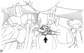
DISCONNECT NO. 2 FUEL PIPE SUB-ASSEMBLY
Disconnect the No. 2 fuel pipe sub-assembly (Click here).
NOTICE:
Check for dirt or other foreign matter on the parts to be disconnected and clean them if necessary.
The fuel tube connector seals with an O-ring. Ensure that there is no damage or foreign matter on the contact surface.
If the connector and the pipe are stuck, push and pull on the connector to release them while pinching the retainer. Pull the connector out of the pipe carefully.
Do not use any tools.
Do not bend or twist the tubes.
Protect the contact surface by covering it with a plastic bag.
Do not damage any of the clips. If a clip is damaged, replace it.
12.
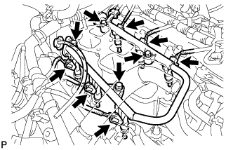
REMOVE FUEL DELIVERY PIPE SUB-ASSEMBLY
Disconnect the 6 fuel injector connectors.
Remove the 4 bolts and fuel delivery pipe together with the 6 fuel injectors.
NOTICE:
Be careful not to drop the injectors when removing the fuel delivery pipe.
13.
REMOVE INTAKE MANIFOLD
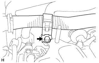
Remove the bolt to separate the wire harness clamp bracket from the intake manifold.
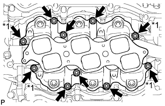
Remove the 4 nuts, 6 bolts and intake manifold from the cylinder head sub-assembly.
Text in Illustration
*1
Nut
Remove the No. 1 intake manifold to head gasket and No. 2 intake manifold to head gasket from the cylinder head sub-assembly.
14.
REMOVE STUD BOLT
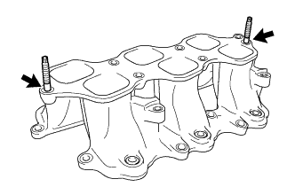
Using an E8 "TORX" socket wrench, remove the 2 stud bolts from the intake manifold.