INSTALLATION
Removal / installation · Vehicles built from Aug 2014
Versions by build date: Aug 2009 – Oct 2010 Nov 2010 – Jul 2014 from Aug 2014
| 1. INSTALL STUD BOLT (w/ Secondary Air Injection System) |

Using an E6 and E10 "TORX" socket wrench, install the 8 stud bolts to the exhaust manifold sub-assembly RH and LH.
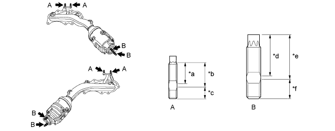

Text in Illustration *a
16.0 mm (0.630 in.)
*b
18.0 mm (0.709 in.)
*c
9.0 mm (0.354 in.)
*d
31.5 mm (1.240 in.)
*e
33.5 mm (1.319 in.)
*f
15.0 mm (0.590 in.)
- Torque:
- Stud Bolt A:
- 5.0 N*m{ 51 kgf*cm , 44 in.*lbf }
- Stud Bolt B:
- 20 N*m{ 204 kgf*cm , 15 ft.*lbf }
| 2. INSTALL STUD BOLT (w/o Secondary Air Injection System) |
Using an E10 "TORX" socket wrench, install the 4 stud bolts to the exhaust manifold sub-assembly RH and LH.
- Torque:
- 20 N*m{ 204 kgf*cm , 15 ft.*lbf }
| 3. INSTALL AIR FUEL RATIO SENSOR (for Bank 2 Sensor 1) |
Using SST, tighten the air fuel ratio sensor.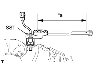
Text in Illustration *a
Fulcrum Length
- SST
- 09224-00010
- Torque:
- without SST:
- 44 N*m{ 449 kgf*cm , 32 ft.*lbf }
- with SST:
- 40 N*m{ 408 kgf*cm , 30 ft.*lbf }
- HINT:
- The "with SST" torque value is effective when using SST with a fulcrum length of 30 mm (1.18 in.).
- The "with SST" torque value is effective when using a torque wrench with a fulcrum length of 300 mm (11.81 in.) (Click here).
- This torque value is effective when SST is parallel to the torque wrench.
- The "with SST" torque value is effective when using SST with a fulcrum length of 30 mm (1.18 in.).
| 4. INSTALL EXHAUST MANIFOLD TO HEAD GASKET LH |
Install a new exhaust manifold to head gasket LH to the cylinder head sub-assembly.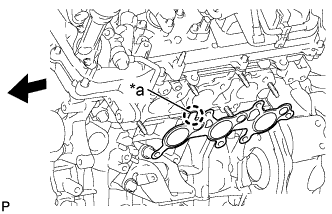
Text in Illustration *a
Protrusion

Front of Vehicle
- NOTICE:
- Install the exhaust manifold to head gasket LH with its protrusion facing towards the front of the vehicle.
| 5. INSTALL EXHAUST MANIFOLD SUB-ASSEMBLY LH (w/ Secondary Air Injection System) |
Temporarily install the exhaust manifold sub-assembly LH to the cylinder head sub-assembly with 6 new nuts.
Install and uniformly tighten the 6 nuts in several steps in the sequence shown in the illustration.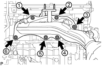
- Torque:
- 21 N*m{ 214 kgf*cm , 15 ft.*lbf }
Connect the air fuel ratio sensor connector.
| 6. INSTALL NO. 2 AIR TUBE (w/ Secondary Air Injection System) |
Install 2 new gaskets to the No. 2 air tube.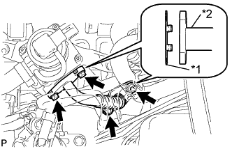
Text in Illustration *1
Gasket
*2
No. 2 Air Tube
Install the No. 2 air tube to the No. 2 emission control valve set and exhaust manifold sub-assembly LH with the 2 bolts and 2 nuts.
- Torque:
- 10 N*m{ 102 kgf*cm , 7 ft.*lbf }
| 7. INSTALL EXHAUST MANIFOLD SUB-ASSEMBLY LH (w/o Secondary Air Injection System) |
Temporarily install the exhaust manifold sub-assembly LH to the cylinder head sub-assembly with 6 new nuts.
Install and uniformly tighten the 6 nuts in several steps in the sequence shown in the illustration.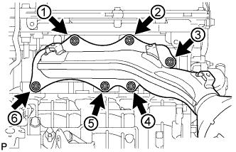
- Torque:
- 21 N*m{ 214 kgf*cm , 15 ft.*lbf }
Connect the air fuel ratio sensor connector.
| 8. INSTALL NO. 2 EXHAUST MANIFOLD HEAT INSULATOR |
Install the No. 2 exhaust manifold heat insulator to the exhaust manifold sub-assembly LH with the 3 bolts.
- Torque:
- 13 N*m{ 133 kgf*cm , 10 ft.*lbf }
| 9. INSTALL NO. 2 MANIFOLD STAY |
Install the No. 2 manifold stay to the exhaust manifold sub-assembly LH with the 3 bolts.
- Torque:
- 40 N*m{ 408 kgf*cm , 30 ft.*lbf }
| 10. INSTALL AIR FUEL RATIO SENSOR (for Bank 1 Sensor 1) |
Using SST, tighten the air fuel ratio sensor.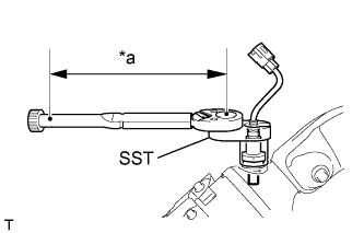
Text in Illustration *a
Fulcrum Length
- SST
- 09224-00010
- Torque:
- without SST:
- 44 N*m{ 449 kgf*cm , 32 ft.*lbf }
- with SST:
- 40 N*m{ 408 kgf*cm , 30 ft.*lbf }
- HINT:
- The "with SST" torque value is effective when using SST with a fulcrum length of 30 mm (1.18 in.).
- The "with SST" torque value is effective when using a torque wrench with a fulcrum length of 300 mm (11.81 in.) (Click here).
- This torque value is effective when SST is parallel to the torque wrench.
- The "with SST" torque value is effective when using SST with a fulcrum length of 30 mm (1.18 in.).
| 11. INSTALL EXHAUST MANIFOLD TO HEAD GASKET |
Install a new exhaust manifold to head gasket to the cylinder head sub-assembly.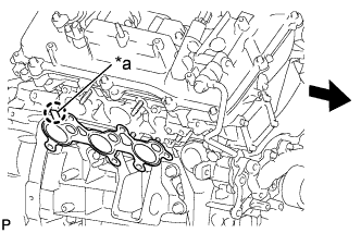
Text in Illustration *a
Protrusion
Front of Vehicle
- NOTICE:
- Install the exhaust manifold to head gasket with its protrusion facing towards the rear of the vehicle.
| 12. INSTALL EXHAUST MANIFOLD SUB-ASSEMBLY RH (w/ Secondary Air Injection System) |
Temporarily install the exhaust manifold sub-assembly RH to the cylinder head sub-assembly with 6 new nuts.
Install and uniformly tighten the 6 nuts in several steps in the sequence shown in the illustration.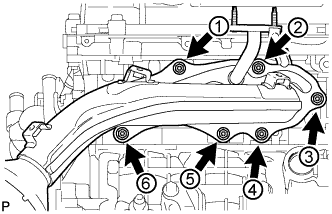
- Torque:
- 21 N*m{ 214 kgf*cm , 15 ft.*lbf }
Connect the air fuel ratio sensor connector.
| 13. INSTALL AIR TUBE (w/ Secondary Air Injection System) |
Install 2 new gaskets to the air tube.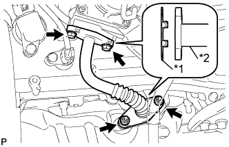
Text in Illustration *1
Gasket
*2
Air Tube
Install the air tube to the No. 1 emission control valve set and exhaust manifold sub-assembly RH with the 2 bolts and 2 nuts.
- Torque:
- 10 N*m{ 102 kgf*cm , 7 ft.*lbf }
| 14. INSTALL EXHAUST MANIFOLD SUB-ASSEMBLY RH (w/o Secondary Air Injection System) |
Temporarily install the exhaust manifold sub-assembly RH to the cylinder head sub-assembly with 6 new nuts.
Install and uniformly tighten the 6 nuts in several steps in the sequence shown in the illustration.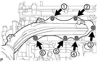
- Torque:
- 21 N*m{ 214 kgf*cm , 15 ft.*lbf }
Connect the air fuel ratio sensor connector.
| 15. INSTALL NO. 1 EXHAUST MANIFOLD HEAT INSULATOR |
Install the No. 1 exhaust manifold heat insulator to the exhaust manifold sub-assembly RH with the 3 bolts.
- Torque:
- 13 N*m{ 133 kgf*cm , 10 ft.*lbf }
| 16. INSTALL MANIFOLD STAY |
Install the manifold stay to the exhaust manifold sub-assembly RH with the 3 bolts.
- Torque:
- 40 N*m{ 408 kgf*cm , 30 ft.*lbf }
| 17. INSTALL FRONT EXHAUST PIPE ASSEMBLY |
Using a vernier caliper, measure the free length of the compression springs.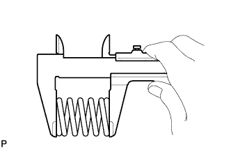
- Free Length of Compression Spring:
Transmission Type
Identification Color
Standard Length
Minimum Length
Manual Transmission
White
40.36 mm (1.58 in.)
38.86 mm (1.53 in.)
Automatic Transmission
Blue
43 mm (1.69 in.)
41.5 mm (1.63 in.)
Automatic Transmission
Pink
40 mm (1.57 in.)
38.5 mm (1.52 in.)
Automatic Transmission
None
42 mm (1.65 in.)
40.5 mm (1.59 in.)
By hand, insert a new gasket to the rear flange of the front exhaust pipe assembly.
Using a plastic hammer, place a wooden block against the gasket and gradually tap in the gasket all the way to the edge of the front exhaust pipe assembly flange.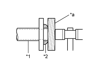
Text in Illustration *1
Front Exhaust Pipe Assembly
*2
Gasket
*a
Wooden Block
- NOTICE:
- Make sure that the gasket is in the correct direction when installing.
- Do not reuse the removed gasket.
- When installing the front exhaust pipe assembly, do not use the center exhaust pipe assembly to press in the gasket.
- Make sure that the gasket is in the correct direction when installing.
Install a new gasket to the front flange of the front exhaust pipe assembly.
Install the front exhaust pipe assembly to the exhaust manifold sub-assembly RH with 2 new nuts.
- Torque:
- 54 N*m{ 554 kgf*cm , 40 ft.*lbf }
Connect the front exhaust pipe assembly to the center exhaust pipe assembly with the 2 bolts and 2 compression springs.
- Torque:
- 43 N*m{ 438 kgf*cm , 32 ft.*lbf }
Connect the heated oxygen sensor connector.
| 18. INSTALL FRONT NO. 2 EXHAUST PIPE ASSEMBLY |
Install the 2 new gaskets to the front No. 2 exhaust pipe assembly.
Install the front No. 2 exhaust pipe assembly to the exhaust pipe support.
Connect the front No. 2 exhaust pipe assembly to the exhaust manifold sub-assembly LH with 2 new nuts.
- Torque:
- 54 N*m{ 554 kgf*cm , 40 ft.*lbf }
Connect the front No. 2 exhaust pipe assembly to the front exhaust pipe assembly with the 2 bolts.
- Torque:
- 48 N*m{ 489 kgf*cm , 35 ft.*lbf }
Connect the heated oxygen sensor connector.
| 19. INSTALL EXHAUST PIPE STOPPER BRACKET |
Install the exhaust pipe stopper bracket to the frame sub-assembly with the 2 bolts.
- Torque:
- 19 N*m{ 194 kgf*cm , 14 ft.*lbf }
| 20. CONNECT STEERING SLIDING YOKE (for RHD) |
Align the matchmarks on the steering sliding yoke and No. 2 steering intermediate shaft sub-assembly.
Install the steering sliding yoke to the No. 2 steering intermediate shaft sub-assembly.
Install the 2 bolts to the steering sliding yoke.
- Torque:
- 36 N*m{ 367 kgf*cm , 27 ft.*lbf }
| 21. INSTALL AIR CLEANER CASE SUB-ASSEMBLY |
Install the air cleaner case sub-assembly with the 3 bolts.
| 22. INSTALL AIR CLEANER FILTER ELEMENT SUB-ASSEMBLY |
Install the air cleaner filter element sub-assembly to the air cleaner case sub-assembly.
| 23. INSTALL AIR CLEANER CAP SUB-ASSEMBLY WITH NO. 1 AIR CLEANER HOSE |
Install the air cleaner cap with the 4 hinges.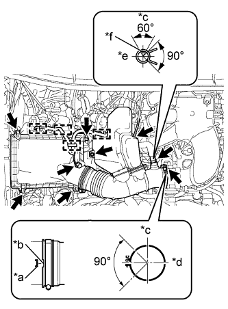
Install the No. 1 air cleaner hose with the clamp.
- Torque:
- 5.0 N*m{ 51 kgf*cm , 44 in.*lbf }
Text in Illustration *a
Protrusion
*b
Groove
*c
Top
*d
Front
*e
RH
*f
Paint mark of the hose
Install the bolt.
- Torque:
- 5.0 N*m{ 51 kgf*cm , 44 in.*lbf }
Connect the ventilation hose and vacuum hose.
- HINT:
- The direction of the hose clamp is indicated in the illustration.
Engage the 4 wire harness clamps.
Connect the MAF meter connector.
| 24. INSTALL V-BANK COVER |
Engage the 2 hooks to install the V-bank cover to the No. 1 V-bank cover bracket.
Align the 2 cushions of the V-bank cover with the 2 pins and press down on the V-bank cover to engage the 2 cushions to the 2 pins.
| 25. INSPECT FOR EXHAUST GAS LEAK |
| 26. INSTALL FRONT FENDER REAR SPLASH SHIELD LH |
Install the front fender rear splash shield LH to the front fender apron sub-assembly LH with the 5 clips.
| 27. INSTALL FRONT FENDER APRON SEAL LH |
Install the front fender apron seal LH to the front fender apron sub-assembly LH with the 5 clips.
| 28. INSTALL FRONT FENDER REAR SPLASH SHIELD RH |
Install the front fender rear splash shield RH to the front fender apron sub-assembly RH with the 5 clips.
| 29. INSTALL FRONT FENDER APRON SEAL RH |
Install the front fender apron seal RH to the front fender apron sub-assembly RH with the 4 clips.