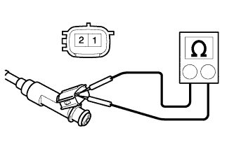
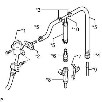
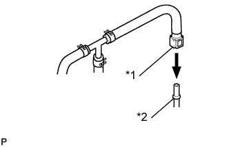
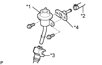
Assemble SST as shown in the illustration.
Discharge the fuel system pressure (Click here).
Disconnect the fuel inlet hose (fuel tube connector) from the fuel pipe.
Remove the bolt and disconnect the fuel pressure regulator from the fuel delivery pipe .
- NOTICE:
- Do not disconnect the No. 2 fuel pipe from the fuel pressure regulator.
Connect SST to the fuel pipe.
- SST
- 09268-31013
(09268-41500)
Text in Illustration
*1
| SST (Fuel Tube Connector)
|
*2
| Fuel Pipe
|
- CAUTION:
- Always read the precautions before connecting the fuel tube connector.
Connect SST (hose) to the fuel inlet of the pressure regulator with another SST (union) and the 2 bolts.
- SST
- 09268-31013
(09268-41091, 95336-08070)
Text in Illustration
*1
| Fuel Pressure Regulator
|
*2
| SST (Hose)
|
*3
| No. 2 Fuel Pipe Sub-assembly
|
*4
| SST (Union)
|
-
Torque:
- 9.0 N*m{
92 kgf*cm
, 80 in.*lbf
}
Connect the fuel return hose to the fuel outlet of the pressure regulator.
Install a new O-ring to the injector.
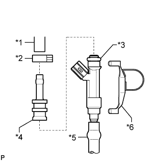
Connect SST (adapter and hose) to the injector, and hold the injector and adapter with SST (clamp).
- SST
- 09268-31013
(09268-41141, 09268-41410, 90467-13001, 95336-08070)
Text in Illustration
*1
| SST (Hose)
|
*2
| SST (Clip)
|
*3
| O-ring
|
*4
| SST (Adapter)
|
*5
| Vinyl Tube
|
*6
| SST (Clamp)
|
Put the injector into a graduated cylinder.
- CAUTION:
- Install a suitable vinyl tube onto the injector assembly to prevent gasoline splashes.
Operate the fuel pump .
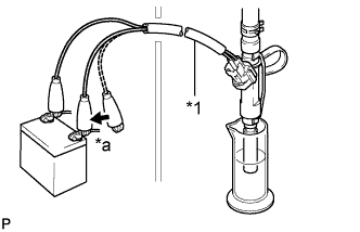
Connect SST (wire) to the injector and the battery for 15 seconds, and measure the injection volume with a graduated cylinder. Test each injector 2 or 3 times.
- SST
- 09842-30080
Text in Illustration
*1
| SST (Wire)
|
*a
| Connect
|
- Standard injection volume:
- 71 to 86 cm3 (4.3 to 5.2 cu. in.) per 15 seconds
- Difference between each injector:
- 15 cm3 (0.9 cu. in.) or less
- NOTICE:
- Always turn the voltage on and off on the battery side, not the fuel pump side.
If the result is not as specified, replace the injector assembly.
- HINT:
- Perform "Inspection After Repairs" after replacing the fuel injector assembly (Click here).