 |
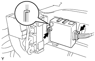
Insert the hook into the instrument panel reinforcement hole and install the clearance warning ECU with the nut.
- Torque:
- 12.5 N*m{ 125 kgf*cm , 9 ft.*lbf }
CLEARANCE WARNING ECU > INSTALLATION |
| 1. INSTALL CLEARANCE WARNING ECU ASSEMBLY |
|
Insert the hook into the instrument panel reinforcement hole and install the clearance warning ECU with the nut.
Connect the clearance warning ECU connector.
| 2. INSTALL INSTRUMENT PANEL SUB-ASSEMBLY |
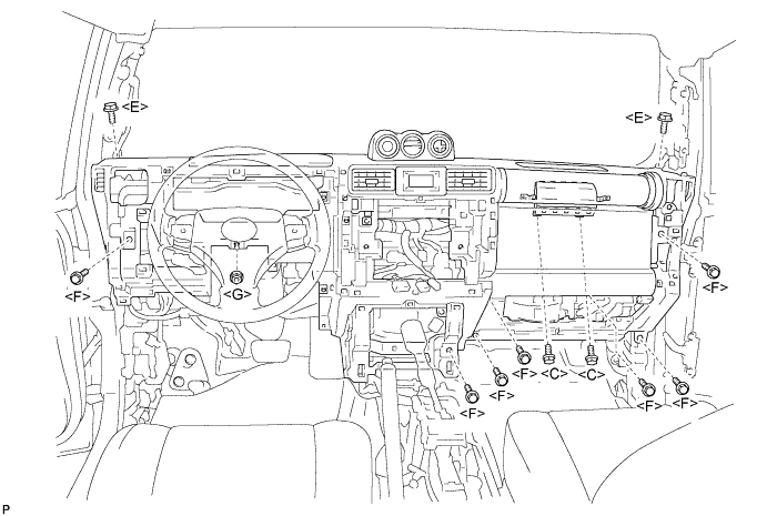
Install the lower instrument panel with the 2 <C> bolts, 2 <E> bolts, 7 <F> bolts and nut <G>.
Engage the clamps and connect the connectors.
| 3. CONNECT PASSENGER AIRBAG CONNECTOR |
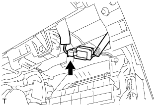 |
Connect the passenger airbag connector.
| 4. INSTALL INSTRUMENT PANEL FINISH PANEL END |
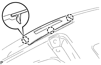 |
Engage the 3 claws and install the instrument panel finish panel end.
| 5. INSTALL FRONT NO. 2 SPEAKER ASSEMBLY |
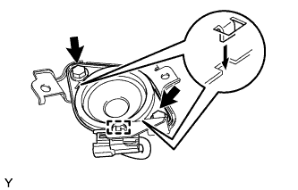 |
Engage the clamp.
Insert the 2 hooks into the 2 cutouts of the front speaker bracket and install the front No. 2 speaker with the 2 bolts.
| 6. INSTALL INSTRUMENT PANEL SPEAKER PANEL SUB-ASSEMBLY RH |
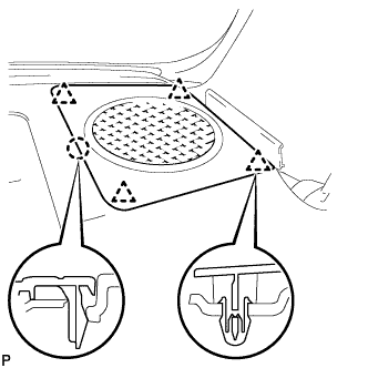 |
Engage the 4 clips and claw and install the instrument panel speaker panel.
| 7. INSTALL INSTRUMENT PANEL SPEAKER PANEL SUB-ASSEMBLY LH |
| 8. INSTALL INSTRUMENT PANEL REGISTER ASSEMBLY RH |
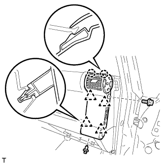 |
Engage the 4 clips and 2 claws and install the instrument panel register.
Install the bolt <F> and clip.
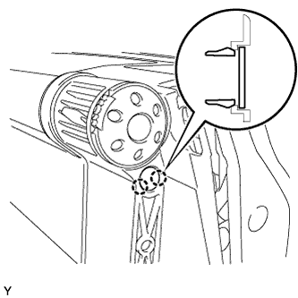 |
Engage the 2 claws and install the instrument panel hole cover.
| 9. INSTALL INSTRUMENT PANEL LOWER FINISH PANEL SUB-ASSEMBLY RH |
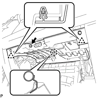 |
Install the connectors to the instrument panel lower finish panel.
Engage the claw and 2 clips and install the instrument panel lower finish panel.
Install screw <A>.
| 10. INSTALL GLOVE COMPARTMENT DOOR ASSEMBLY |
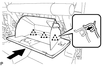 |
Install the glove compartment door assembly with the 3 hinges while holding it horizontal.
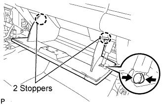 |
Slightly flex the upper part of the glove compartment door assembly, and install the glove compartment door assembly.
Install the glove compartment door stoppers onto the glove compartment door.
| 11. INSTALL COMBINATION METER ASSEMBLY |
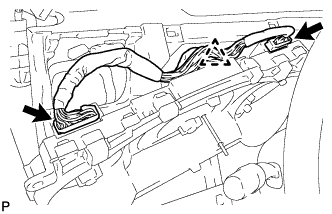 |
Connect the 2 connectors and the clamp.
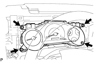 |
Install the combination meter assembly with the 4 screws.
| 12. INSTALL INSTRUMENT CLUSTER LOWER FINISH PANEL |
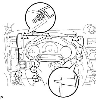 |
Connect the connectors.
Engage the 3 clips and 4 claws and install the instrument cluster lower finish panel.
| 13. INSTALL INSTRUMENT LOWER PANEL |
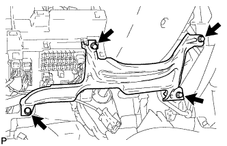 |
Install the lower instrument panel with the 4 <F> bolts.
| 14. INSTALL INSTRUMENT PANEL LOWER FINISH PANEL SUB-ASSEMBLY LH |
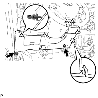 |
Engage the 5 clips and claw and install the lower instrument panel finish panel.
Connect the connector.
Install the 2 <F> bolts.
| 15. INSTALL HOOD LOCK CONTROL LEVER SUB-ASSEMBLY |
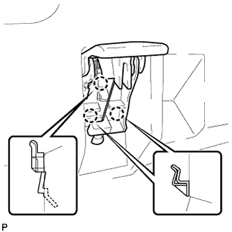 |
Engage the 3 claws and install the hood lock control lever.
| 16. INSTALL INSTRUMENT PANEL REGISTER ASSEMBLY LH |
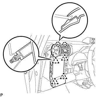 |
Engage the 4 clips and 2 claws and install the instrument panel register.
| 17. INSTALL INSTRUMENT LOWER COVER SUB-ASSEMBLY |
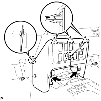 |
Engage the 3 clips and 2 claws and install the instrument lower cover.
Install the 2 <F> bolts and 2 clips.
| 18. INSTALL FRONT CONSOLE BOX UPPER PANEL GARNISH |
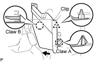 |
Slide the console upper panel garnish toward the front of the vehicle and engage claw B.
Engage the claw and clip and install the console upper panel garnish.
| 19. INSTALL FRONT CONSOLE BOX |
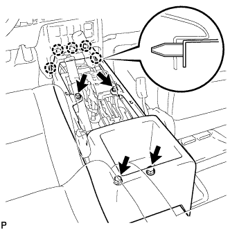 |
Engage the 5 claws and install the front console box.
Install the 4 <D> screws.
| 20. INSTALL FRONT CONSOLE BOX BOTTOM MAT |
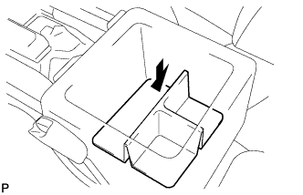 |
Install the box bottom mat.
| 21. INSTALL FRONT CONSOLE BOX UPPER PANEL SUB-ASSEMBLY |
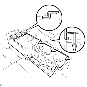 |
Engage the 3 claws and 5 clips and install the console upper rear panel.
| 22. INSTALL SHIFT LEVER KNOB SUB-ASSEMBLY (for 4WD) |
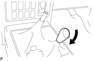 |
Install the shift lever knob.
| 23. INSTALL SHIFT LEVER KNOB SUB-ASSEMBLY (for Manual Transmission) |
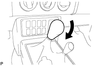 |
Install the shift lever knob.
| 24. INSTALL PARKING BRAKE HOLE COVER SUB-ASSEMBLY |
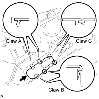 |
Slide the parking brake hole cover toward the rear of the vehicle and engage the 2 C claws.
Engage the 4 claws and install the parking brake hole cover.
| 25. INSTALL RADIO RECEIVER ASSEMBLY |
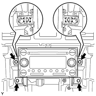 |
Connect the connectors.
Align the 2 bosses of the radio bracket with the hole in the instrument panel and install the radio receiver with the 4 bolts.
| 26. INSTALL INTEGRATION CONTROL PANEL ASSEMBLY |
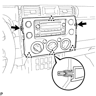 |
Connect the 3 connectors.
Engage the 4 clips and install the integration control panel assembly.
Install the 2 <H> screws.
| 27. INSTALL INSTRUMENT PANEL GARNISH LH |
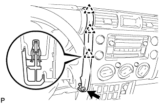 |
Engage the 3 clips and install the instrument panel garnish.
Install 2 <H> screws.
| 28. INSTALL INSTRUMENT PANEL GARNISH RH |
| 29. INSTALL ASSIST GRIP RETAINER RH |
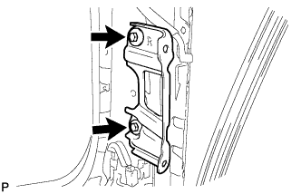 |
Install the assist grip retainer with the 2 bolts.
| 30. INSTALL ASSIST GRIP RETAINER LH |
| 31. INSTALL FRONT PILLAR GARNISH RH |
Engage the guide and the 2 clips and install the front pillar garnish.
| 32. INSTALL FRONT PILLAR GARNISH LH |
| 33. INSTALL ASSIST GRIP ASSEMBLY |
Install the assist grip with the 2 bolts.
| 34. INSTALL ASSIST GRIP PLUG |
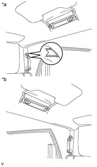 |
| *a | for RH Side |
| *b | for LH Side |
Engage the 2 claws and install the assist grip plug.
| 35. INSTALL FRONT DOOR OPENING TRIM WEATHERSTRIP RH |
Install the front door opening trim weatherstrip.
| 36. INSTALL FRONT DOOR OPENING TRIM WEATHERSTRIP LH |
Install the front door opening trim weatherstrip.
| 37. INSTALL COWL SIDE TRIM BOARD RH |
Engage the 2 claws and install the cowl side trim board.
Install the clip.
| 38. INSTALL COWL SIDE TRIM BOARD LH |
| 39. INSTALL FOOTREST CLIP |
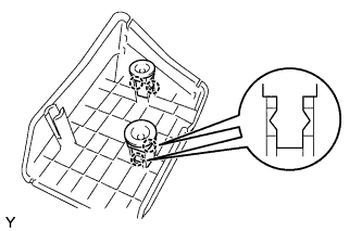 |
Engage the 2 claws and install the footrest clip.
| 40. INSTALL FRONT FLOOR FOOTREST |
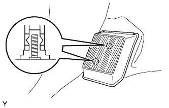 |
Engage the 2 studs and install the front floor footrest.
| 41. INSTALL FRONT DOOR SCUFF PLATE RH |
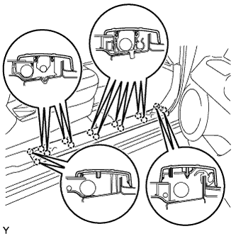 |
Engage the 14 claws and install the door scuff plate.
| 42. INSTALL FRONT DOOR SCUFF PLATE LH |
| 43. CONNECT CABLE TO NEGATIVE BATTERY TERMINAL |
| 44. INSPECT SRS WARNING LIGHT |