 |
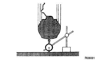
Using a dial indicator, check the tire runout.
- Tire runout:
- 3.0 mm (0.118 in.) or less
FRONT WHEEL ALIGNMENT > ADJUSTMENT |
| 1. INSPECT TIRES |
Check the tires for wear and proper inflation pressure.
| Tire Size | Front Wheel kPa (kgf/cm2, psi) | Rear Wheel kPa (kgf/cm2, psi) |
| P265/70R17 113S | 220 (2.2, 32) | 220 (2.2, 32) |
| 265/70R17 115S | 220 (2.2, 32) | 220 (2.2, 32) |
|
Using a dial indicator, check the tire runout.
| 2. MEASURE VEHICLE HEIGHT |
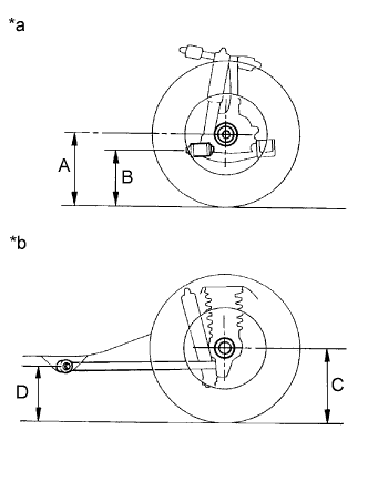 |
| *a | Front Side |
| *b | Rear Side |
| Vehicle Model | A-B | C-D |
| GSJ10L-GKASKA | 116.1 mm (4.57 in.) | 81.5 mm (3.21 in.) |
| GSJ15L-GKFSKA | 87.1 mm (3.43 in.) | 61.1 mm (2.41 in.) |
| GSJ15L-GKASKA | 87.2 mm (3.43 in.) | 61.4 mm (2.42 in.) |
| Vehicle Model | A-B | C-D |
| GSJ15L-GKFSKA | 87.1 mm (3.43 in.) | 61.1 mm (2.41 in.) |
| GSJ15L-GKASKA | 87.2 mm (3.43 in.) | 61.4 mm (2.42 in.) |
| 3. INSPECT WHEEL TURNING ANGLE |
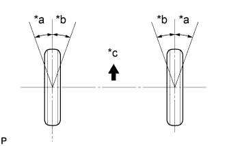 |
Turn the steering wheel fully, and measure the wheel turning angle.
| *a | Inside |
| *b | Outside |
| *c | Front of the Vehicle |
| Vehicle Model | Inside wheel | Outside wheel (Reference) |
| GSJ10L-GKASKA | 32°45' (30°45' to 33°45') 32.74° (30.74° to 33.74°) | 28°56' (28.93°) |
| GSJ15L-GKFSKA | 33°10' (31°10' to 34°10') 33.17° (31.17° to 34.17°) | 29°38' (29.63°) |
| GSJ15L-GKASKA | 33°10' (31°10' to 34°10') 33.16° (31.16° to 34.16°) | 29°38' (29.63°) |
| Vehicle Model | Inside wheel | Outside wheel (Reference) |
| GSJ15L-GKFSKA | 33°10' (31°10' to 34°10') 33.17° (31.17° to 34.17°) | 29°38' (29.63°) |
| GSJ15L-GKASKA | 33°10' (31°10' to 34°10') 33.16° (31.16° to 34.16°) | 29°38' (29.63°) |
| 4. INSPECT CAMBER, CASTER AND STEERING AXIS INCLINATION |
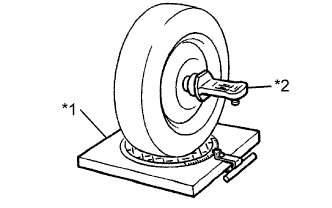 |
Install the camber-caster-kingpin gauge and position the front wheel on the wheel alignment tester.
| *1 | Wheel Alignment Tester |
| *2 | Gauge |
Inspect the camber, caster and steering axis inclination.
| Vehicle Model | Camber | Caster | Steering Axis Inclination |
| GSJ10L-GKASKA | -1°04' to -0°04' (-1.06°to 0.06°) | 3°43' to 4°43' (3.72°to 4.72°) | 12°35' to 13°35' (12.58°to 13.58°) |
| GSJ15L-GKFSKA | -0°21' to 0°39' (-0.36°to 0.64°) | 2°47' to 3°47' (2.78°to 3.78°) | 11°51' to 12°51' (11.85°to 12.85°) |
| GSJ15L-GKASKA | -0°21' to 0°39' (-0.36°to 0.64°) | 2°47' to 3°47' (2.79°to 3.79°) | 11°51' to 12°51' (11.85°to 12.85°) |
| Vehicle Model | Camber | Caster | Steering Axis Inclination |
| GSJ15L-GKFSKA | -0°21' to 0°39' (-0.36°to 0.64°) | 2°47' to 3°47' (2.79°to 3.79°) | 11°51' to 12°51' (11.85°to 12.85°) |
| GSJ15L-GKASKA | -0°21' to 0°39' (-0.36°to 0.64°) | 2°47' to 3°47' (2.79°to 3.79°) | 11°51' to 12°51' (11.85°to 12.85°) |
| 5. ADJUST CAMBER AND CASTER |
Loosen the nut and bolt.
Turn camber adjust cam No. 2 and the toe adjust cam and adjust the camber and the caster.
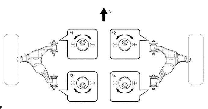
| *1 | Front Cam (LH) | *2 | Front Cam (RH) |
| *3 | Rear Cam (LH) | *4 | Rear Cam (RH) |
| *a | Front | - | - |
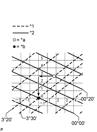 |
How to read the adjustment chart (using examples).
| *1 | Caster |
| *2 | Camber |
| *a | Calculated Value |
| *b | 0 Point |
Measure the present alignment.
Calculate the difference between the standard value (A) and the measured value (B) on the adjustment chart.
As shown in the chart, read the distance from the marked point to 0 point, and adjust the front and/or rear adjusting cams accordingly.
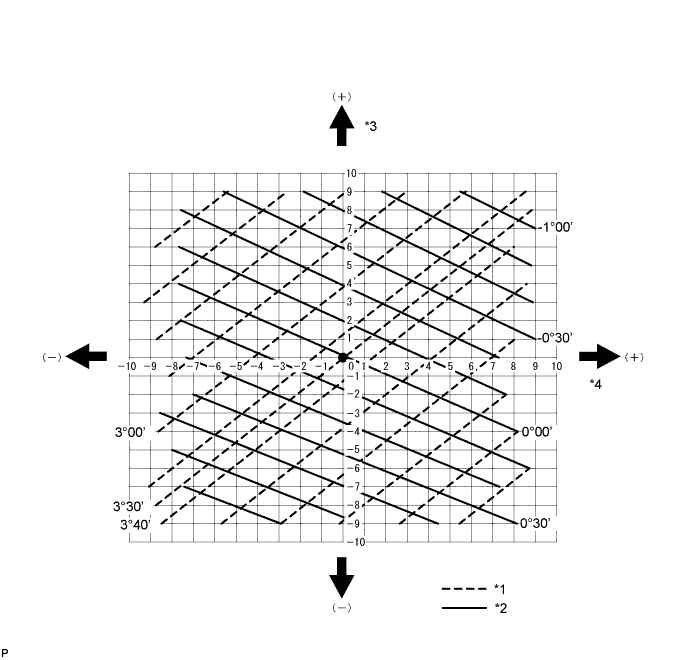
| *1 | Caster | *2 | Camber |
| *3 | Front Cam Gradation | *4 | Rear Cam Gradation |
| 6. INSPECT TOE-IN |
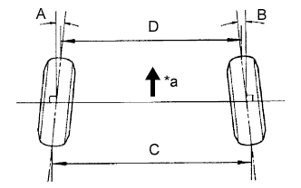 |
| *a | Front |
| A+B | C-D |
| -0°05' to 0°15' (-0.08° to 0.24°) | -1.0 to 3.0 mm (-0.04 to 0.12 in.) |
| 7. ADJUST TOE-IN |
Remove the rack boot set clips.
Loosen the tie rod end lock nuts.
Turn the right and left rack ends uniformly to adjust the toe-in.
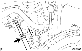 |
Make sure that the lengths of the right and left rack ends are the same.
Tighten the tie rod end lock nuts.
Place the boots on the seats and install the clips.
| 8. FRONT WHEELS FACING STRAIGHT AHEAD |
| 9. DISCONNECT CABLE FROM NEGATIVE BATTERY TERMINAL (w/ VSC) |
| 10. CONNECT CABLE TO NEGATIVE BATTERY TERMINAL (w/ VSC) |
| 11. PERFORM YAW RATE SENSOR ZERO POINT CALIBRATION (w/ VSC) |
| 12. CHECK STEERING ANGLE SENSOR ZERO POINT CALIBRATION (w/ VSC) |