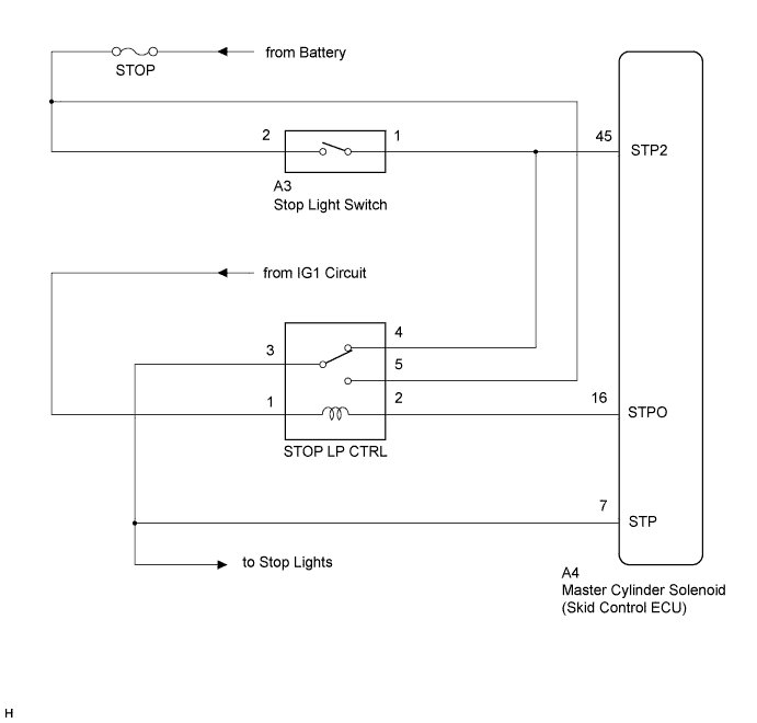
DTC C1380 Stop Light Control Relay Malfunction |
| DTC Code | DTC Detection Condition | Trouble Area |
| C1380 | Either condition is met:
|
|
| 1.CHECK STOP LIGHT SWITCH OPERATION |
Check that the stop lights come on when the brake pedal is depressed and go off when the brake pedal is released.
|
| ||||
| OK | |
 |
| 2.INSPECT SKID CONTROL ECU (STP TERMINAL) |
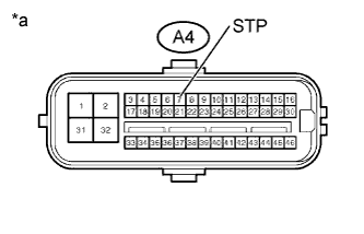 |
Disconnect the skid control ECU connector.
Measure the voltage according to the value(s) in the table below.
| Tester Connection | Condition | Specified Condition |
| A4-7 (STP) - Body ground | Brake pedal depressed | 8 to 14 V |
| A4-7 (STP) - Body ground | Brake pedal released | Below 1.5 V |
| *a | Front view of wire harness connector (to Skid Control ECU) |
|
| ||||
| OK | |
|
| 3.INSPECT SKID CONTROL ECU (STP2 TERMINAL) |
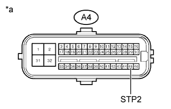 |
Disconnect the skid control ECU connector.
Measure the voltage according to the value(s) in the table below.
| Tester Connection | Condition | Specified Condition |
| A4-45 (STP2 )- Body ground | Brake pedal depressed | 8 to 14 V |
| A4-45 (STP2 )- Body ground | Brake pedal released | Below 1.5 V |
|
| ||||
| OK | |
|
| 4.PERFORM ACTIVE TEST USING TECHSTREAM (STOP LIGHT RELAY) |
Turn the ignition switch off.
Connect the Techstream to the DLC3.
Turn the ignition switch to ON.
Turn the Techstream on.
Enter the following menus: Chassis / ABS/VSC/TRAC / Active Test.
| Tester Display | Test Part | Control Range | Diagnostic Note |
| Stop Light Relay | Stop light relay | Stop light relay ON or OFF | Observe stop lights |
Check that the stop lights turn on and off on the rear combination light when using the Techstream.
|
| ||||
| OK | |
|
| 5.RECONFIRM DTC |
| Result | Proceed to |
| DTC is output | A |
| DTC is not output | B |
|
| ||||
| A | ||
 | ||
| ||
| 6.CHECK STOP LP CTRL RELAY |
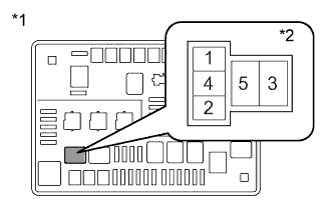 |
Remove the STOP LP CTRL relay from the engine room relay block.
Measure the voltage according to the value(s) in the table below.
| Tester Connection | Switch Condition | Specified Condition |
| 1 - Body ground | Ignition switch ON | 8 to 14 V |
| 5 - Body ground | Always | 11 to 14 V |
| *1 | Engine Room Relay Block |
| *2 | STOP LP CTRL Relay Holder |
|
| ||||
| OK | |
|
| 7.INSPECT STOP LP CTRL RELAY |
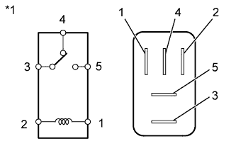 |
Remove the STOP LP CTRL relay from the engine room R/B No. 2.
Measure the resistance according to the value(s) in the table below.
| Tester Connection | Condition | Specified Condition |
| 3 - 4 | Battery voltage not applied | Below 1 Ω |
| Battery voltage applied to terminal 1 and 2 | 10 kΩ or higher | |
| 3 - 5 | Battery voltage not applied | 10 kΩ or higher |
| Battery voltage applied to terminal 1 and 2 | Below 1 Ω |
| *1 | STOP LP CTRL Relay |
|
| ||||
| OK | |
|
| 8.INSPECT SKID CONTROL ECU (STPO TERMINAL) |
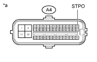 |
Disconnect the skid control ECU connector.
Measure the voltage according to the value(s) in the table below.
| Tester Connection | Switch Condition | Specified Condition |
| A4-16 (STPO) - Body ground | Ignition switch ON | 11 to 14 V |
| *a | Front view of wire harness connector (to Skid Control ECU) |
|
| ||||
| OK | |
|
| 9.RECONFIRM DTC |
Clear the DTCs (Click here).
Turn the ignition switch off.
Check if the same DTC is output (Click here).
| Result | Proceed to |
| DTC is output | A |
| DTC is not output | B |
|
| ||||
| A | ||
| ||
| ||
| 10.INSPECT STOP LP CTRL RELAY |
|
Remove the STOP LP CTRL relay from the engine room R/B No. 2.
Measure the resistance according to the value(s) in the table below.
| Tester Connection | Condition | Specified Condition |
| 3 - 4 | Battery voltage not applied | Below 1 Ω |
| Battery voltage applied to terminal 1 and 2 | 10 kΩ or higher | |
| 3 - 5 | Battery voltage not applied | 10 kΩ or higher |
| Battery voltage applied to terminal 1 and 2 | Below 1 Ω |
| *1 | STOP LP CTRL Relay |
|
| ||||
| OK | ||
| ||
| ||

