| B |  |
| GO TO DTC CHART (Click here) |
DTC P0751 Shift Solenoid "A" Performance (Shift Solenoid Valve S1) |
| DTC No. | DTC Detection Conditions | Trouble Areas |
| P0751 | Gear required by the ECM does not match the actual gear when driving. (2 trip detection logic) |
|
| Related DTCs | P0751: Shift solenoid valve S1/OFF malfunction Shift solenoid valve S1/ON malfunction |
| Required sensors/Components (Main) | Shift solenoid valve S1 |
| Required sensors/Components (Related) | Vehicle speed sensor, Throttle position sensor, Speed sensor (NT), Speed sensor (SP2) |
| Frequency of operation | Continuous |
| Duration | OFF malfunctions (A) and (B): 0.4 seconds OFF malfunction (C): Immediate ON malfunctions (A), (B) and (C): 0.4 seconds ON malfunction (D): 3 seconds ON malfunction (E): 0.5 seconds |
| MIL operation | 2 driving cycles |
| Sequence of operation | None |
| The monitor will run whenever the following DTCs are not present | P0717 (Turbine speed sensor (NT) circuit) P0722 (Output speed sensor (SP2) circuit) P0973, P0974 (Shift solenoid "A" (S1) circuit) P0976, P0977 (Shift solenoid "B" (S2) circuit) P0985, P0986 (Shift solenoid "E" (SR) circuit) P0748 (Pressure control solenoid "A" (SL1) circuit) P0778 (Pressure control solenoid "B" (SL2) circuit) P0128 (ECT (Engine Coolant Temperature) sensor circuit) P0327, P0328, P0332, P0333 (Knock sensor circuit) |
| ETCS (Electronic Throttle Control System) | Not system down |
| Transmission shift position | "D" |
| Duration time from shifting "N" to "D" | 4 seconds or more |
| ECT | 40°C (104°F) or more |
| Spark advance from max. retard timing by knock sensor control | 0° CA or more |
| Engine | Starting |
| Transfer range | High |
| ECM selected gear | 1st |
| Vehicle speed | 2 to 40 km/h (1.2 to 24.9 mph) |
| Throttle valve opening angle | 8% or more (when actual gear 4th) 6.5% or more at engine speed of 2000 rpm (Conditions vary with engine speed) |
| Current ECM selected gear | 5th |
| Last ECM selected gear | 4th |
| Continuous time of ECM selecting 4th gear | 2 seconds or more |
| Actual gear when ECM selected 4th gear | 4th |
| Current ECM selected gear | 5th |
| Last ECM selected gear | 4th |
| ECM selected gear | 1st |
| Vehicle speed | 2 to 40 km/h (1.2 to 24.9 mph) |
| Throttle valve opening angle | 8% or more 6.5% or more at engine speed of 2000 rpm (Conditions vary with engine speed) |
| ECM selected gear | 4th |
| Vehicle speed | 2 km/h (1.2 mph) or more |
| Throttle valve opening angle | 6.5% or more at engine speed of 2000 rpm (Conditions vary with engine speed) |
| ECM selected gear | 3rd |
| Vehicle speed | 2 km/h (1.2 mph) or more |
| Throttle valve opening angle | 6.5% or more at engine speed of 2000 rpm (Conditions vary with engine speed) |
| Current ECM selected gear | 5th |
| Last ECM selected gear | 4th |
| Vehicle speed (During transition from 4th to 5th gear) | Less than 100 km/h (62.2 mph) |
| ECM selected gear | 5th |
| Engine speed - Turbine speed (NE - NT) (After transition from 4th to 5th gear) | 150 rpm or less |
| Vehicle speed (After transition from 4th to 5th gear) | Less than 100 km/h (62.2 mph) |
| Turbine speed/Output speed | 0.93 to 1.07 (Actual gear is 4th) |
| Turbine speed/Output speed | 0.65 to 0.79 (Actual gear is 5th) |
| Output record from ECM for 4th → 5th up-shifting | Recorded |
| Turbine speed/Output speed | 3.30 to 7.50 (Actual gear is 1st) |
| Turbine speed/Output speed | 3.30 to 7.50 (Actual gear is 1st) |
| Turbine speed/Output speed | 1.91 to 2.35 (Actual gear is 2nd) |
| Turbine speed - Output speed x 4th gear ratio | 1000 rpm or more |
| Turbine speed - Output speed x 5th gear ratio | 1000 rpm or more |
| Tester Display | Test Part | Control Range | Diagnostic Note |
| Control the Shift Position | Operate shift solenoid valve and set each shift position by yourself |
| Possible to check operation of shift solenoid valves [Vehicle Condition] 50 km/h (30 mph) or less |
| Gearshift controlled by ECM | 1st | 2nd | 3rd | 4th | 5th |
| Shift solenoid valve S1 | ON | ON | OFF | OFF | OFF |
| 1.CHECK ANY OTHER DTCS OUTPUT (IN ADDITION TO DTC P0751) |
Connect the Techstream to the DLC3.
Turn the ignition switch to ON.
Turn the Techstream on.
Enter the following menus: Powertrain / Engine and ECT / Trouble Codes.
Read the DTCs using the Techstream.
| Result | Proceed to |
| Only P0751 is output | A |
| P0751 and other DTCs are output | B |
|
| ||||
| A | |
 |
| 2.PERFORM ACTIVE TEST USING TECHSTREAM (ACTIVE THE SOLENOID (SLT)) |
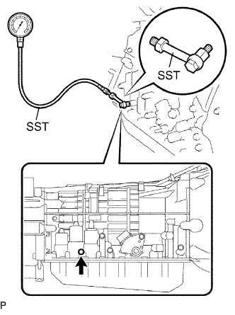 |
Remove the test plug on the transmission case center right side and connect SST.
Connect a Techstream to the DLC3.
Start the engine and warm it up.
Measure the line pressure with SST.
Turn the Techstream on.
Enter the following menus: Powertrain / Engine and ECT / Active Test.
According to the display on the Techstream, perform the Active Test.
Measure the line pressure with SST.
| Tester Display | Test Part | Control Range | Diagnostic Note |
| Active the Solenoid (SLT)* | Operate the shift solenoid SLT and raise line pressure | ON or OFF
| [Vehicle Condition]
|
|
| ||||
| OK | |
|
| 3.INSPECT SHIFT SOLENOID VALVE S1 |
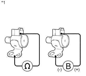 |
Remove the shift solenoid valve S1.
Measure the resistance according to the value(s) in the table below.
| Tester Connection | Condition | Specified Condition |
| Shift solenoid S1 connector - Shift solenoid S1 body | 20°C (68°F) | 11 to 15 Ω |
| *1 | Component without harness connected: (Shift Solenoid S1) |
Connect the positive (+) lead to the terminal of the solenoid connector, and the negative (-) lead to the solenoid body.
|
| ||||
| OK | |
|
| 4.INSPECT TRANSMISSION VALVE BODY ASSEMBLY |
Check the transmission valve body assembly.
|
| ||||
| OK | ||
 | ||
| ||