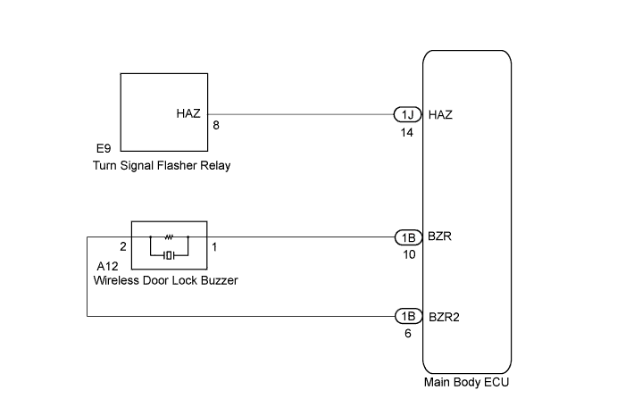
WIRELESS DOOR LOCK CONTROL SYSTEM > No Answer-Back |
| 1.CHECK WIRELESS DOOR LOCK CONTROL FUNCTIONS |
Check the wireless door lock functions by operating the transmitter switches.
| Result | Proceed to |
| Wireless door lock functions are normal | A |
| Wireless door lock functions are abnormal | B |
|
| ||||
| A | |
 |
| 2.PERFORM ACTIVE TEST USING TECHSTREAM (WIRELESS DOOR LOCK BUZZER, FLASHER RELAY) |
Connect a Techstream to the DLC3.
Turn the ignition switch to ON.
Turn the tester ON.
Enter the following menus: Body Electrical / Main Body / Active Test.
According to the display on tester, perform the "Active Test".
| Tester Display | Test Part | Control Range | Diagnostic Note |
| Hazard | Flasher relay | ON or OFF | - |
| Wireless Buzzer | Sounds wireless buzzer | ON or OFF | - |
| Result | Proceed to |
| Hazard warning light answer-back function does not operate | A |
| Wireless door lock buzzer answer-back function does not operate | B |
|
| ||||
| A | |
|
| 3.CHECK HAZARD WARNING LIGHTS |
Check that the hazard warning lights flash when the hazard warning signal switch is pressed.
|
| ||||
| OK | ||
 | ||
| ||
| 4.INSPECT WIRELESS DOOR LOCK BUZZER |
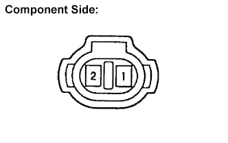 |
Disconnect the A12 wireless door lock buzzer connector.
Measure the resistance.
| Tester Connection | Specified Condition |
| 1 - 2 | Approximately 1 kΩ |
Reconnect the wireless door lock buzzer connector.
|
| ||||
| OK | |
|
| 5.CHECK HARNESS AND CONNECTOR (WIRELESS DOOR LOCK BUZZER - MAIN BODY ECU) |
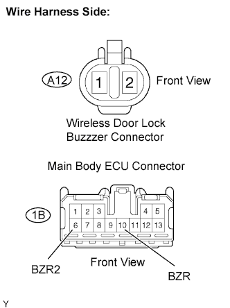 |
Disconnect the A12 wireless door lock buzzer connector.
Disconnect the 1B main body ECU connector.
Measure the resistance.
| Tester Connection | Specified Condition |
| 1B-10 (BZR) - A12-1 | Below 1 Ω |
| 1B-6 (BZR2) - A12-2 | Below 1 Ω |
| 1B-10 (BZR) orA12-1 - Body ground | 10 kΩ or higher |
| 1B-6 (BZR2) or A12-2 - Body ground | 10 kΩ or higher |
Reconnect the buzzer connector.
Reconnect the main body ECU connector.
|
| ||||
| OK | ||
| ||
| ||

