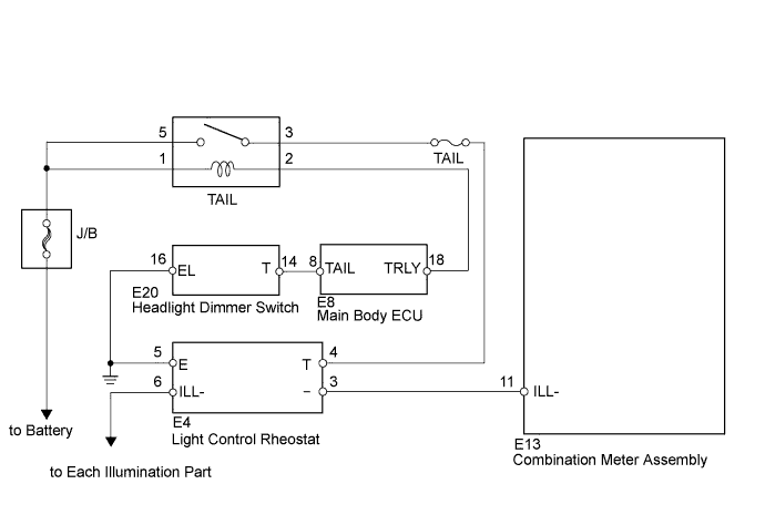
METER / GAUGE SYSTEM > Operating Light Control Rheostat does not Change Light Brightness |
| 1.CHECK HARNESS AND CONNECTOR (FUSE (TAIL) - RHEOSTAT, RHEOSTAT - BODY GROUND) |
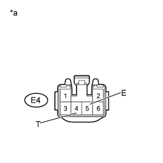 |
Disconnect the E4 light control rheostat connector.
Measure the voltage according to the value(s) in the table below.
| Tester Connection | Switch Condition | Specified Condition |
| E4-4 (T) - Body ground | Tail light ON | 11 to 14 V |
Measure the resistance according to the value(s) in the table below.
| Tester Connection | Condition | Specified Condition |
| E4-5 (E) - Body ground | Always | Below 1 Ω |
| *a | Front view of wire harness connector (to Light Control Rheostat) |
Reconnect the light control rheostat connector.
|
| ||||
| OK | |
 |
| 2.INSPECT LIGHT CONTROL RHEOSTAT |
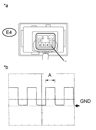 |
Remove the light control rheostat but without disconnecting the connector (Click here).
Turn the ignition switch to ON.
Using an oscilloscope, check the signal waveform of the light control rheostat.
| Item | Contents |
| Terminal connection | E4-3 (-) - Body ground |
| Tool setting | 5 V / DIV, 50 ms / DIV |
| Vehicle condition | Ignition switch ON |
| *a | Component with harness connected (Light Control Rheostat) |
| *b | Waveform |
Reinstall the light control rheostat.
|
| ||||
| OK | |
|
| 3.CHECK HARNESS AND CONNECTOR (COMBINATION METER ASSEMBLY - LIGHT CONTROL RHEOSTAT) |
Disconnect the E13 combination meter assembly connector.
Disconnect the E4 light control rheostat connector.
Measure the resistance according to the value(s) in the table below.
| Tester Connection | Condition | Specified Condition |
| E13-11 (ILL-) - E4-3 (-) | Always | Below 1 Ω |
Reconnect the combination meter assembly connector.
Reconnect the light control rheostat connector.
|
| ||||
| OK | ||
 | ||
| ||
