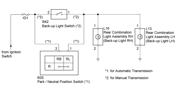
LIGHTING SYSTEM > Back-up Light Circuit |
| 1.INSPECT FUSE (IG1) |
Remove the IG1 fuse from the main body ECU.
Measure the resistance according value(s) in the table below.
| Tester Connection | Condition | Specified Condition |
| IG1 fuse | Always | Below 1 Ω |
Reinstall the IG1 fuse.
|
| ||||
| OK | |
 |
| 2.INSPECT BULB (BACK-UP LIGHT BULB) |
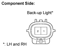 |
Remove the back-up light bulb.
Apply battery voltage to the terminals and check that the back-up light illuminates.
| Measurement Condition | Specified Condition |
| Positive battery - Terminal 1 Negative battery - Terminal 2 | back-up light illuminates |
Reinstall the back-up light bulb.
|
| ||||
| OK | |
|
| 3.CHECK TRANSAXLE TYPE |
Check the vehicle's transaxle type.
| Transaxle Type | Proceed To |
| Automatic Transmission | A |
| manual Transmission | B |
|
| ||||
| A | |
|
| 4.INSPECT PARK / NEUTRAL POSITION SWITCH |
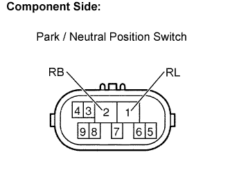 |
Disconnect the B35 park / neutral position switch.
Measure the resistance according value(s) in the table below.
| Tester Connection | Shift Position | Specified Connection |
| 2 (RB) - 1 (RL) | R | Below 1 Ω |
| 2 (RB) - 1 (RL) | Except R | 10 kΩ or higher |
Reconnect the park / neutral position switch.
| Result | Proceed to |
| OK | A |
| NG (for Four-wheel drive model) | B |
| NG (except Four-wheel drive model) | C |
|
| ||||
|
| ||||
| A | |
|
| 5.CHECK HARNESS AND CONNECTOR (FUSE - PARK / NEUTRAL POSITION SWITCH) |
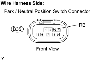 |
Disconnect the B35 park / neutral position switch connector.
Measure the voltage according value(s) in the table below.
| Tester Connection | Condition | Specified Condition |
| B35-2 (RB) - Body ground | Ignition switch ON | 11 to 14 V |
Reconnect the park / neutral position switch connector.
|
| ||||
| OK | |
|
| 6.CHECK HARNESS AND CONNECTOR (PARK / NEUTRAL POSITION SWITCH - REAR BACK-UP LIGHT) |
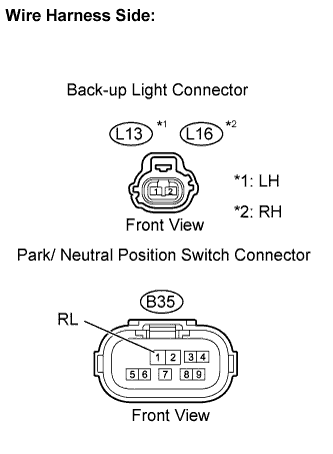 |
Disconnect the B35 park / neutral position switch connector.
Disconnect the L13 and L16 back-up light connectors.
Measure the resistance according value(s) in the table below.
| Tester Connection | Condition | Specified Condition |
| B35-1 (RL) - L13-1 | Always | Below 1 Ω |
| B35-1 (RL) - L16-1 | Always | Below 1 Ω |
| L13-1 - Body ground | Always | 10 kΩ or higher |
| L16-1 - Body ground | Always | 10 kΩ or higher |
Reconnect the park / neutral position switch connector.
Reconnect the back-up light connectors.
|
| ||||
| OK | ||
 | ||
| ||
| 7.INSPECT BACK-UP LIGHT SWITCH |
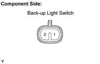 |
Disconnect the B42 back-up light switch connector.
Measure the resistance according value(s) in the table below.
| Tester Connection | Shift Position | Specified Connection |
| 1 - 2 | R | Below 1 Ω |
| 1 - 2 | Except R | 10 kΩ or higher |
Reconnect the back-up light switch connector.
|
| ||||
| OK | |
|
| 8.CHECK HARNESS AND CONNECTOR (FUSE - BACK-UP LIGHT SWITCH) |
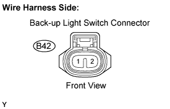 |
Disconnect the B42 back-up light switch connector.
Measure the voltage according value(s) in the table below.
| Tester Connection | Condition | Specified Condition |
| B42-2 - Body ground | Ignition switch ON | 11 to 14 V |
Reconnect the back-up light switch connector.
|
| ||||
| OK | |
|
| 9.CHECK HARNESS AND CONNECTOR (BACK-UP LIGHT SWITCH - BACK-UP LIGHT) |
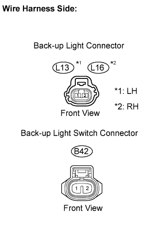 |
Disconnect the B42 back-up light switch connector.
Disconnect the L13 and L16 back-up light connectors.
Measure the resistance according value(s) in the table below.
| Tester Connection | Condition | Specified Condition |
| B42-1 - L13-1 | Always | Below 1 Ω |
| B42-1 - L16-1 | Always | Below 1 Ω |
| L13-1 - Body ground | Always | 10 kΩ or higher |
| L16-1 - Body ground | Always | 10 kΩ or higher |
Reconnect the back-up light switch connector.
Reconnect the back-up light connectors.
|
| ||||
| OK | ||
| ||
| ||

