TIRE PRESSURE WARNING VALVE AND TRANSMITTER > INSTALLATION |
| 1. INSTALL TIRE PRESSURE WARNING VALVE AND TRANSMITTER |
Install a new grommet to the tire pressure warning valve and transmitter.
![]() |
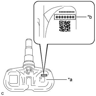
Insert the tire pressure warning valve and transmitter into the valve installation hole. Insert from the inside of the rim so that the print surface can be seen.
| *a | Printed Surface |
| *b | 7-digit Number Transmitter ID |
![]() |
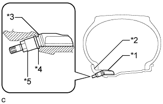
From the outside of the rim, install the washer onto the tire pressure warning valve and transmitter, and tighten the nut.
| *1 | Tire Pressure Warning Valve and Transmitter |
| *2 | Rim |
| *3 | Grommet |
| *4 | Washer |
| *5 | Nut |
![]() |
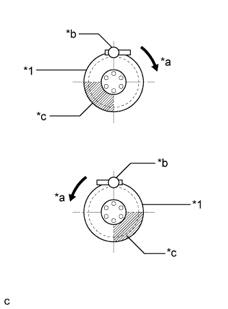
Set the wheel onto the mounting machine and install the lower bead. Position the main body of the tire pressure warning valve and transmitter in the shaded area shown in the illustration.
| *1 | Rim |
| *a | Rim Rotating Direction |
| *b | Mount Tool of the Mounting Machine |
| *c | Area for Tire Pressure Warning Valve and Transmitter |
Install the upper bead.
Install a new valve core.
After the tire is inflated, the valve nut may be loose. Retighten the nut to the specified torque.
Check for air leaks with soapy water.
If there is air leakage, push the valve core 2 or 3 times to remove any dirt attached to the valve core. If air continues to leak, replace the grommet, washer and nut.
Install the cap.
| 2. INSTALL FRONT WHEEL |
| 3. INSTALL REAR WHEEL |
| 4. INSPECT TIRES |
Check the tires for wear and proper inflation pressure.
| Tire Size | Front Wheel kPa (kgf/cm2, psi) | Rear Wheel kPa (kgf/cm2, psi) |
| P265/70R17 113S | 220 (2.2, 32) | 220 (2.2, 32) |
| 265/70R17 115S | 220 (2.2, 32) | 220 (2.2, 32) |
![]() |
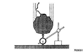
Using a dial indicator, check the tire runout.
| 5. REGISTRATION TRANSMITTED ID |
| 6. PERFORM INITIALIZATION |
| 7. INSPECT TIRE PRESSURE WARNING SYSTEM |