 |
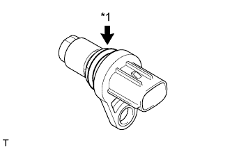
Apply a light coat of engine oil to the O-ring of the VVT sensor.
| *1 | O-Ring |
- NOTICE:
- When reusing the VVT sensor, inspect the O-ring.
- If the O-ring has scratches or cuts, replace the VVT sensor.
VVT SENSOR > INSTALLATION |
| 1. INSTALL VVT SENSOR (for Exhaust Side of Bank 2) |
|
Apply a light coat of engine oil to the O-ring of the VVT sensor.
| *1 | O-Ring |
Install the VVT sensor to the cylinder head cover sub-assembly with the bolt.
Connect the VVT sensor connector.
| 2. INSTALL VVT SENSOR (for Intake Side of Bank 2) |
Apply a light coat of engine oil to the O-ring of the VVT sensor.
Install the VVT sensor to the cylinder head cover sub-assembly with the bolt.
Connect the VVT sensor connector.
| 3. INSTALL VVT SENSOR (for Exhaust Side of Bank 1) |
Apply a light coat of engine oil to the O-ring of the VVT sensor.
Install the VVT sensor to the cylinder head cover sub-assembly with the bolt.
Connect the VVT sensor connector.
| 4. INSTALL VVT SENSOR (for Intake Side of Bank 1) |
Apply a light coat of engine oil to the O-ring of the VVT sensor.
Install the VVT sensor to the cylinder head cover sub-assembly with the bolt.
Connect the VVT sensor connector.
| 5. INSTALL AIR CLEANER HOSE ASSEMBLY |
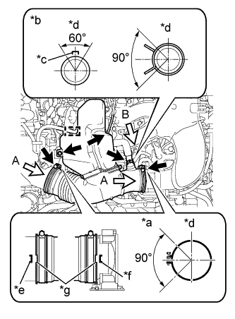 |
Install the air cleaner hose assembly to the air cleaner cap sub-assembly and intake air surge tank with the 2 hose clamps.
| *a | View A |
| *b | View B |
| *c | Hose Paint Mark |
| *d | Upper of Vehicle |
| *e | Protrusion of Air Cleaner Cap Sub-assembly |
| *f | Protrusion of Intake Air Surge Tank |
| *g | Indentation of Air Hose Assembly |
Connect the air cleaner hose assembly to the resonator bracket with the bolt.
Engage the clamp and connect the wire harness to the air cleaner hose assembly.
Connect the vacuum hose to the air cleaner hose assembly.
Connect the ventilation hose to the air cleaner hose assembly with the hose clip.
| 6. INSTALL NO. 2 EMISSION CONTROL VALVE SET |