CYLINDER HEAD GASKET > INSTALLATION |
| 1. INSPECT CYLINDER HEAD SET BOLT |
|
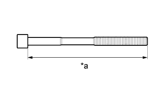
Using a vernier caliper, measure the length of the cylinder head set bolt from the seat to the end.
| *a | Measurement Length |
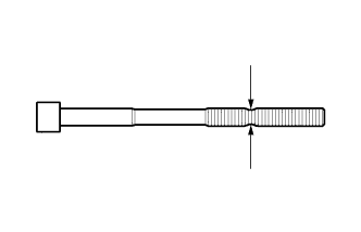 |
Using a vernier caliper, measure the diameter of the elongated thread at the narrowest visible area.
| 2. INSPECT CYLINDER HEAD SUB-ASSEMBLY |
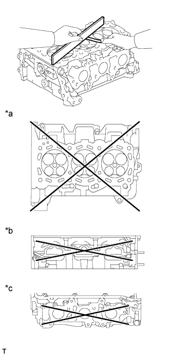 |
Using a precision straightedge and feeler gauge, measure the warpage of the surfaces which contact the cylinder block sub-assembly and manifolds.
| *a | Cylinder Block Side: |
| *b | Intake Side: |
| *c | Exhaust Side: |
| Item | Specified Condition |
| Cylinder block side | 0.05 mm (0.00197 in.) |
| Intake side | 0.08 mm (0.00315 in.) |
| Exhaust side | 0.08 mm (0.00315 in.) |
| Item | Specified Condition |
| Cylinder block side | 0.10 mm (0.00394 in.) |
| Intake side | 0.10 mm (0.00394 in.) |
| Exhaust side | 0.10 mm (0.00394 in.) |
Using a dye penetrant, check the intake ports, exhaust ports and cylinder surface for cracks.
If cracked, replace the cylinder head sub-assembly.
| 3. INSTALL CYLINDER HEAD GASKET |
Remove any old seal packing material and be careful not to drop any oil on the contact surfaces of the cylinder head or cylinder block.
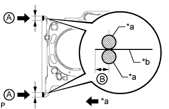 |
Apply seal packing to a new cylinder head gasket as shown in the illustration.
| *a | Seal Packing |
| *b | Gasket |
| A | 10 to 15 mm (0.394 to 0.591 in.) |
| B | 1.25 to 1.5 mm (0.0492 to 0.0591 in.) |
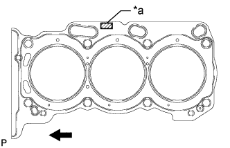 |
Place the cylinder head gasket on the cylinder block surface with the front face of the Lot No. stamp upward.
| *a | Lot No. |
 | Engine Front |
| 4. INSTALL CYLINDER HEAD SUB-ASSEMBLY |
Place the cylinder head on the cylinder block.
Apply a light coat of engine oil to the threads and under the heads of the cylinder head bolts.
Step 1:
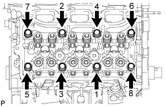 |
Using a 10 mm bi-hexagon wrench, install and uniformly tighten the 8 cylinder head bolts with the plate washers in several steps and in the sequence shown in the illustration.
Step 2:
Mark the front side of each cylinder head bolt head with paint.
Tighten the cylinder head bolts another 90°.
Step 3:
Tighten the cylinder head bolts an additional 90°.
Check that the paint mark is now at a 180° angle to the front.
| 5. INSTALL NO. 2 CYLINDER HEAD GASKET |
Remove any old seal packing material and be careful not to drop any oil on the contact surfaces of the cylinder head or cylinder block.
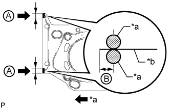 |
Apply seal packing to a new cylinder head gasket as shown in the illustration.
| *a | Seal Packing |
| *b | Gasket |
| A | 10 to 15 mm (0.394 to 0.591 in.) |
| B | 1.25 to 1.5 mm (0.0492 to 0.0591 in.) |
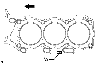 |
Place the cylinder head gasket on the cylinder block surface with the front face of the Lot No. stamp upward.
| *a | Lot No. |
| Engine Front |
| 6. INSTALL CYLINDER HEAD LH |
Place the cylinder head on the cylinder block.
Apply a light coat of engine oil to the threads and under the heads of the cylinder head bolts.
Step 1:
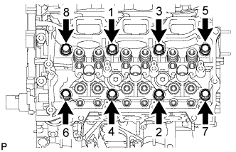 |
Using a 10 mm bi-hexagon wrench, install and uniformly tighten the 8 cylinder head bolts with the plate washers in several steps in the sequence shown in the illustration.
Step 2:
Mark the front side of each cylinder head bolt head with paint.
Tighten the cylinder head bolts another 90°.
Step 3:
Tighten the cylinder head bolts an additional 90°.
Check that the paint mark is now at a 180° angle to the front.
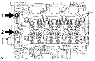 |
Tighten the 2 bolts in the order shown in the illustration.
| 7. INSTALL VALVE STEM CAP |
Apply a light coat of engine oil to the 24 valve stem caps.
Install the 24 valve stem caps to the cylinder head sub-assembly and cylinder head LH.
| 8. INSTALL VALVE LASH ADJUSTER ASSEMBLY |
Inspect the 24 valve lash adjuster assemblies .
Install the 24 valve lash adjuster assemblies to the cylinder head sub-assembly and cylinder head LH.
| 9. INSTALL NO. 1 VALVE ROCKER ARM SUB-ASSEMBLY |
Apply engine oil to the valve lash adjuster assembly tips and valve stem cap ends.
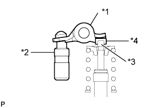 |
Install the 24 No. 1 valve rocker arm sub-assemblies as shown in the illustration.
| *1 | No. 1 Valve Rocker Arm Sub-assembly |
| *2 | Valve Lash Adjuster Assembly |
| *3 | Valve |
| *4 | Valve Stem Cap |
| 10. INSTALL CAMSHAFT BEARING CAP (for Bank 2) |
Apply a light coat of engine oil to the camshaft journals, camshaft housing sub-assembly LH and camshaft bearing caps.
Install the No. 3 camshaft sub-assembly and No. 4 camshaft sub-assembly to the camshaft housing sub-assembly LH.
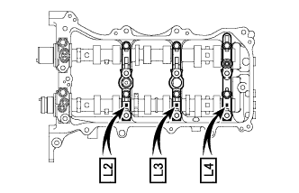 |
Check the marks and numbers on the camshaft bearing caps and place each of them in the proper position facing the proper direction.
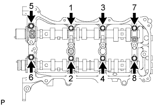 |
Temporarily tighten the 8 bolts in the sequence shown in the illustration.
| 11. INSTALL CAMSHAFT HOUSING SUB-ASSEMBLY LH |
|
Make sure that the No. 1 valve rocker arm sub-assembly is installed as shown in the illustration.
| *1 | No, 1 Valve Rocker Arm Sub-assembly |
| *2 | Valve Lash Adjuster Assembly |
| *3 | Valve |
| *4 | Valve Stem Cap |
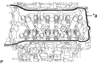 |
Apply seal packing in a continuous line as shown in the illustration.
| *a | Seal Packing |
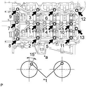 |
Install the camshaft housing sub-assembly LH to the cylinder head LH with the 13 bolts in the sequence shown in the illustration.
| *1 | Knock Pin |
| *a | Front View |
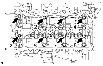 |
Tighten the 8 bolts in the sequence shown in the illustration.
| 12. INSTALL CAMSHAFT BEARING CAP (for Bank 1) |
Apply a light coat of engine oil to the camshaft journals, camshaft housing sub-assembly RH and camshaft bearing caps.
Install the camshaft and No. 2 camshaft to the camshaft housing sub-assembly RH.
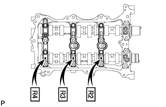 |
Check the marks and numbers on the camshaft bearing caps and place each of them in the proper position facing the proper direction.
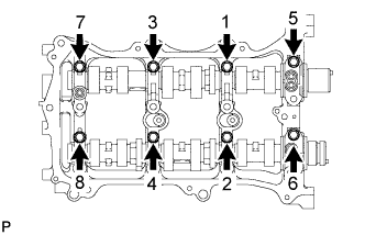 |
Temporarily tighten the 8 camshaft bearing cap bolts in the sequence shown in the illustration.
| 13. INSTALL CAMSHAFT HOUSING SUB-ASSEMBLY RH |
|
Make sure that the No. 1 valve rocker arm sub-assembly is installed as shown in the illustration.
| *1 | No. 1 Valve Rocker Arm Sub-assembly |
| *2 | Valve Lash Adjuster Assembly |
| *3 | Valve |
| *4 | Valve Stem Cap |
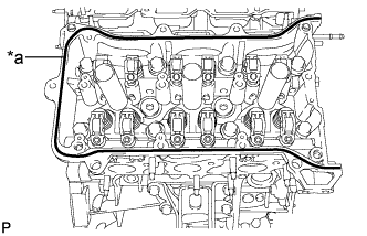 |
Apply seal packing in a continuous line as shown in the illustration.
| *a | Seal Packing |
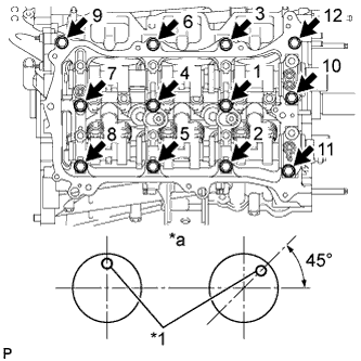 |
Install the camshaft housing sub-assembly RH and tighten the 12 bolts in the sequence shown in the illustration.
| *1 | Knock Pin |
| *a | Front View |
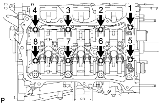 |
Tighten the 8 bolts in the sequence shown in the illustration.
| 14. INSTALL NO. 3 CHAIN TENSIONER ASSEMBLY (for Bank 2) |
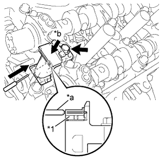 |
Install the No. 3 chain tensioner assembly to the camshaft housing sub-assembly LH with the bolt.
Push in the plunger and insert a pin a of 1.0 mm (0.0394 in.) diameter into the plunger hole to hold the tensioner.
| *1 | Plunger |
| *a | Pin of 1.0 mm (0.0394 in.) diameter |
| *b | Push |
| 15. INSTALL CAMSHAFT TIMING GEARS AND NO. 2 CHAIN (for Bank 2) |
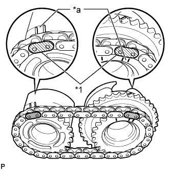 |
Align the mark plates (yellow) with the timing marks of the camshaft timing gear assembly and camshaft timing exhaust gear assembly LH as shown in the illustration.
| *1 | Mark Plate |
| *a | Timing Mark |
Apply a light coat of engine oil to the bolt threads and bolt-seating surface.
Align the knock pin of the No. 3 camshaft sub-assembly and No. 4 camshaft sub-assembly with the pin hole of the camshaft timing gear assembly. Install the camshaft timing gear assembly and camshaft timing exhaust gear LH with the No. 2 chain sub-assembly installed.
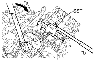 |
Using SST to hold the hexagonal portion of each camshaft, install the 2 bolts of the camshaft timing gear assembly and camshaft timing exhaust gear assembly LH.
| *a | Turn |
| *b | Hold |
Remove the pin from the No. 3 chain tensioner assembly.
| 16. INSTALL NO. 2 CHAIN TENSIONER ASSEMBLY (for Bank 1) |
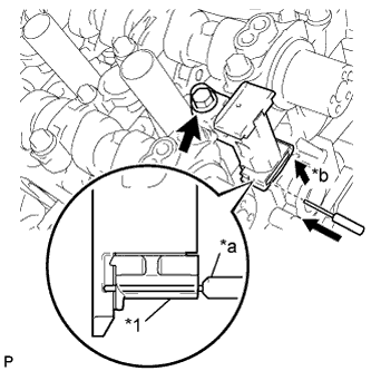 |
Install the No. 2 chain tensioner assembly to the camshaft housing sub-assembly RH with the bolt.
Push in the plunger and insert a pin of 1.0 mm (0.0394 in.) diameter into the plunger hole to hold the tensioner.
| *1 | Plunger |
| *a | Pin of 1.0 mm (0.0394 in.) diameter |
| *b | Push |
| 17. INSTALL CAMSHAFT TIMING GEARS AND NO. 2 CHAIN (for Bank 1) |
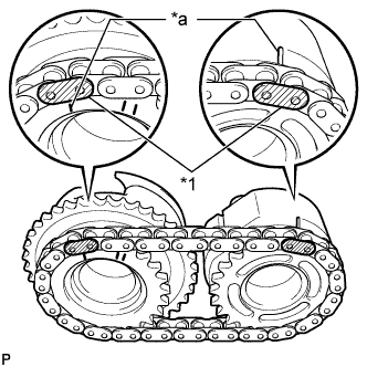 |
Align the mark plates (yellow) with the timing marks of the camshaft timing gear assembly and camshaft timing exhaust gear assembly RH as shown in the illustration.
| *1 | Mark Plate |
| *a | Timing Mark |
Apply a light coat of engine oil to the bolt threads and bolt-seating surface.
Align the knock pin of the camshaft and No. 2 camshaft with the pin hole of the camshaft timing gear assembly. Install the camshaft timing gear assembly and camshaft timing exhaust gear assembly RH with the No. 2 chain sub-assembly installed.
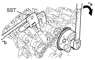 |
Using SST to hold the hexagonal portion of each camshaft, install the 2 bolts of the camshaft timing gear assembly and camshaft timing exhaust gear assembly RH.
| *a | Turn |
| *b | Hold |
Remove the pin from the No. 2 chain tensioner assembly.
| 18. INSTALL NO. 1 CHAIN VIBRATION DAMPER |
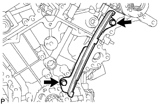 |
Install the No. 1 chain vibration damper to the cylinder block sub-assembly and cylinder head LH with the 2 bolts.
| 19. INSTALL NO. 2 CHAIN VIBRATION DAMPER |
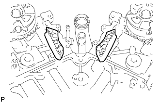 |
Install the 2 No. 2 chain vibration dampers to the cylinder head sub-assembly and cylinder head LH.
| 20. INSTALL CRANKSHAFT TIMING SPROCKET |
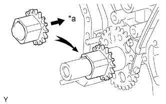 |
Install the crankshaft timing sprocket to the crankshaft with the sprocket facing inward as shown in the illustration.
| *a | Inward |
| 21. INSTALL NO. 1 IDLE GEAR SHAFT |
Apply a light coat of engine oil to the rotating surface of the No. 1 idle gear shaft.
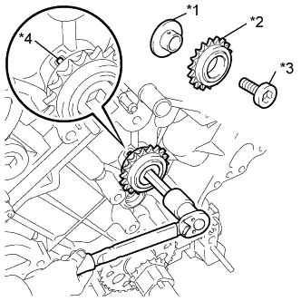 |
Temporarily install the No. 1 idle gear shaft and No. 1 idle gear with the No. 2 idle gear shaft while aligning the knock pin of the No. 1 idle gear shaft with the knock pin groove of the cylinder block sub-assembly.
| *1 | No. 1 Idle Gear Shaft |
| *2 | No. 1 Idle Gear |
| *3 | No. 2 Idle Gear Shaft |
| *4 | Knock Pin |
Using a 10 mm hexagon wrench, tighten the No. 2 idle gear shaft.
| 22. INSTALL CHAIN SUB-ASSEMBLY |
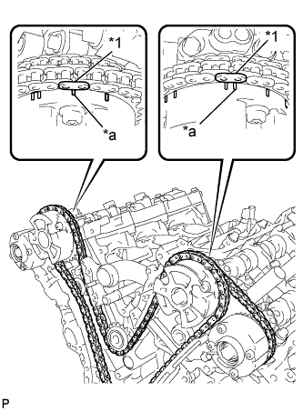 |
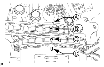
Align the mark plate and timing marks as shown in the illustration and install the chain sub-assembly.
| *1 | Mark Plate |
| *a | Timing Mark |
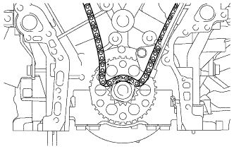 |
Do not pass the chain over the crankshaft, just temporarily place it on the crankshaft timing sprocket.
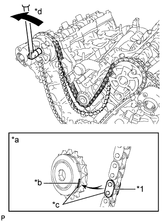 |
Turn the camshaft timing gear assembly on bank 1 counterclockwise to tighten the chain sub-assembly between the banks.
| *1 | Chain Plate |
| *a | When the No. 1 idle gear is reused |
| *b | Mark |
| *c | Align |
| *d | Turn |
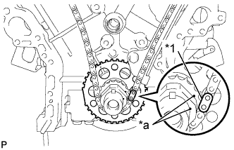 |
Align the mark plate and timing marks as shown in the illustration and install the chain sub-assembly to the crankshaft timing sprocket.
| *1 | Mark Plate |
| *a | Timing Mark |
Temporarily tighten the crankshaft pulley bolt.
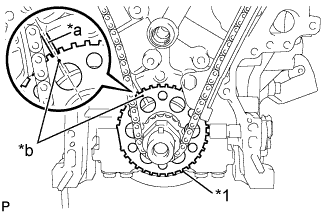 |
Turn the crankshaft clockwise to set it to the RH cylinder block bore center line (TDC/compression).
| *1 | Crank Angle Sensor Plate |
| *a | RH Cylinder Block Bore Center Line |
| *b | Timing Mark |
| 23. INSTALL CHAIN TENSIONER SLIPPER |
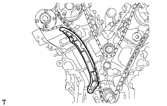 |
Install the chain tensioner slipper to the cylinder block sub-assembly.
| 24. INSTALL NO. 1 CHAIN TENSIONER ASSEMBLY |
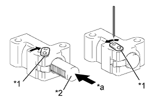 |
Turn the stopper plate of the tensioner clockwise and push in the plunger of the No. 1 chain tensioner assembly as shown in the illustration.
| *1 | Stopper Plate |
| *2 | Plunger |
| *a | Push |
Turn the stopper plate of the tensioner counterclockwise and insert a pin of 1.27 mm (0.05 in.) diameter into the holes on the stopper plate and tensioner to fix the stopper plate in place.
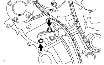 |
Install the No. 1 chain tensioner assembly to the cylinder head sub-assembly with the 2 bolts.
Remove the pin from the No. 1 chain tensioner assembly.
| 25. INSPECT VALVE TIMING |
Check the camshaft timing marks.
Check that each camshaft timing mark is positioned as shown in the illustration.
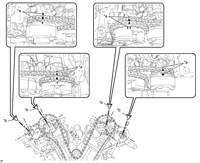
| *a | Timing Mark | *b | Viewpoint |
 |
If the valve timing is misaligned, reinstall the chain sub-assembly.
Remove the crank pulley bolt.
| 26. INSTALL TIMING CHAIN COVER SUB-ASSEMBLY |
Install the timing chain cover (Click here).