OIL PUMP > INSTALLATION |
| 1. INSTALL FRONT CRANKSHAFT OIL SEAL |
|
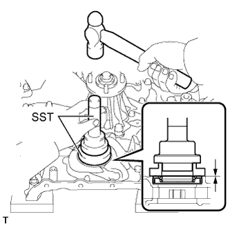
Using SST and a hammer, tap in a new front crankshaft oil seal until its surface is flush with the timing chain cover sub-assembly edge.
| 2. INSTALL TIMING CHAIN COVER SUB-ASSEMBLY |
Remove any old packing (FIPG) material and be careful not to drop any oil on the contact surfaces of the timing chain cover sub-assembly, cylinder head sub-assembly and cylinder block sub-assembly.
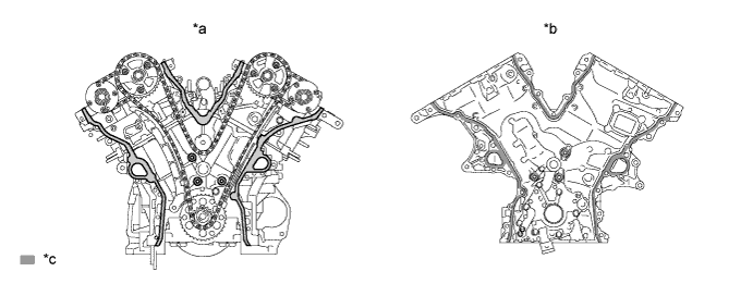
| *a | Cylinder head and cylinder block side: | *b | Timing chain cover side: |
| *c | Clean and degrease | - | - |
Apply a light coat of engine oil to a new oil pump gasket.
Install the oil pump gasket to the cylinder block sub-assembly.
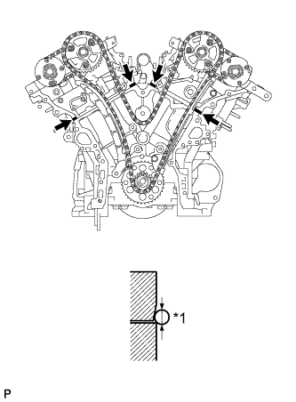 |
Apply seal packing as shown in the illustration.
| *1 | Seal Diameter |
 | Seal Packing |
Apply seal packing in a continuous line to the timing chain cover sub-assembly as shown in the following illustration.
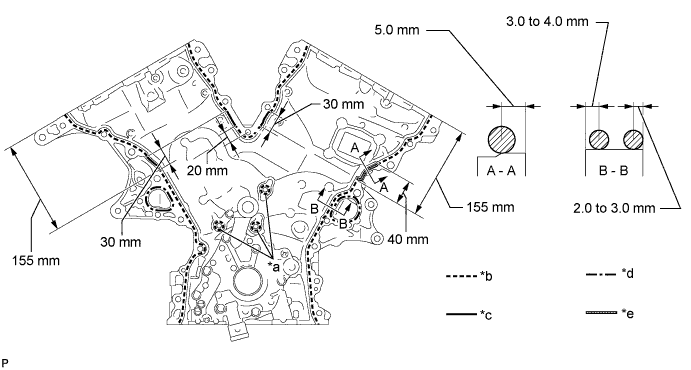
| *a | Be sure to apply seal packing | *b | Dashed line area (Seal packing: Toyota Genuine Seal Packing Black, Three Bond 1207B or equivalent) |
| *c | Continuous line area (Seal packing: Toyota Genuine Seal Packing Black, Three Bond 1207B or equivalent) | *d | Alternate long and short dashed line area (Seal packing: Toyota Genuine Seal Packing 1282B, Three Bond 1282B or equivalent) |
| *e | Diagonal line area (Seal packing: Toyota Genuine Seal Packing Black, Three Bond 1207B or equivalent) | - | - |
| Area | Seal Packing Diameter | Application Position from Inside Seal Line |
| Continuous Line Area | 4.5 mm (0.177 in.) or more | 3.0 to 4.0 mm (0.118 to 0.158 in.) |
| Alternate Long and Short Dashed Line Area | 3.5 mm (0.138 in.) or more | 2.0 to 3.0 mm (0.0787 to 0.118 in.) |
| Dashed Line Area | 3.5 mm (0.138 in.) or more | 3.0 to 4.0 mm (0.118 to 0.158 in.) |
| Diagonal Line Area | 6.0 mm (0.236 in.) or more | 5.0 mm (0.197 in.) |
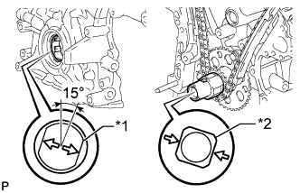 |
Align the oil pump drive rotor spline and the crankshaft as shown in the illustration. Install the spline and timing chain cover sub-assembly to the crankshaft.
| *1 | Drive Rotor Spline |
| *2 | Crankshaft |
Install the timing chain cover sub-assembly with the 26 bolts labeled A, B, C, D and the 2 nuts. Tighten the bolts and nuts uniformly in several steps.
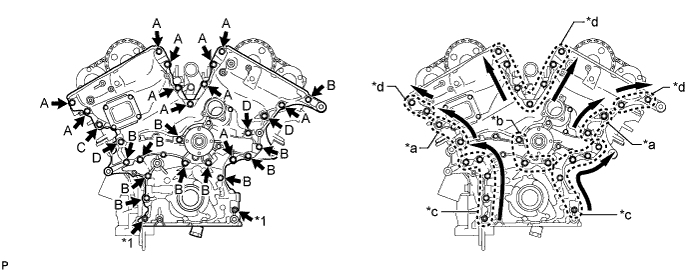
| *1 | Nut | - | - |
| *a | Area 1 | *b | Area 2 |
| *c | Area 3 | *d | Area 4 |
| Item | Length |
| Bolt A | 25 mm (0.984 in.) |
| Bolt B | 55 mm (2.17 in.) |
| Bolt C | 35 mm (1.38 in.) |
| Bolt D | 65 mm (2.56 in.) |
Fully tighten the bolts in Area 1.
Fully tighten the bolts in Area 2.
Fully tighten the bolts in Area 3.
Fully tighten the bolts in Area 4.
| 3. INSTALL OIL PAN SUB-ASSEMBLY |
Remove any old packing (FIPG material) and be careful not to drop any oil on the contact surfaces of the cylinder block sub-assembly, engine rear oil seal retainer and oil pan sub-assembly.
Install 3 new O-rings to the timing chain cover sub-assembly.
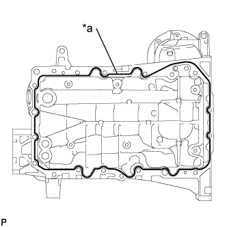 |
Apply seal packing in a continuous line as shown in the illustration.
| *a | Seal Packing |
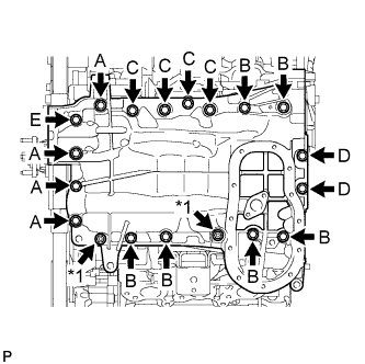 |
Install the oil pan sub-assembly with the 17 bolts (A, B, C, D and E) and 2 nuts. Tighten the bolts and nuts uniformly in several steps.
| *1 | Nut |
| Item | Length |
| Bolt A | 60 mm (2.36 in.) |
| Bolt B | 45 mm (1.77 in.) |
| Bolt C | 25 mm (0.984 in.) |
| Bolt D | 16 mm (0.630 in.) |
| Bolt E | 70 mm (2.76 in.) |
| 4. INSTALL OIL STRAINER SUB-ASSEMBLY |
Install a new gasket and the oil strainer to the oil pan sub-assembly with the 2 nuts.
| 5. INSTALL NO. 2 OIL PAN SUB-ASSEMBLY |
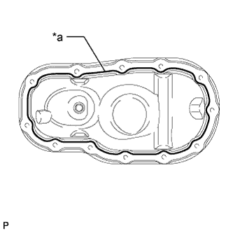 |
Apply seal packing in a continuous line as shown in the illustration.
| *a | Seal Packing |
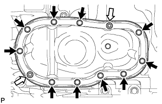 |
Install the No. 2 oil pan sub-assembly with the 10 bolts and 2 nuts. Tighten the bolts and nuts uniformly in several steps.
| Bolt |
 | Nut |
| 6. INSTALL CYLINDER HEAD COVER SUB-ASSEMBLY |
Remove any old packing (FIPG) material and be careful not to drop any oil on the contact surfaces of the cylinder head sub-assembly, timing chain cover sub-assembly or cylinder head cover sub-assembly.
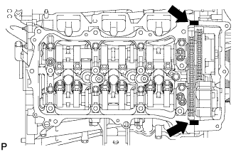 |
Apply seal packing as shown in the illustration.
| Seal Packing |
Install 3 new gaskets to the camshaft bearing cap.
Install a new gasket to the cylinder head cover sub-assembly.
Install a new seal washer to the bolt.
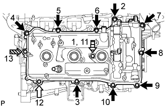 |
Temporarily install the cylinder head cover sub-assembly with the 12 bolts. Tighten the bolts uniformly in several steps.
| Bolt A |
| Bolt B |
 | Bolt C |
 | Bolt D |
| Item | Length |
| A | 25 mm (0.984 in.) |
| B | 35 mm (1.38 in.) |
| C | 65 mm (2.56 in.) |
| D | 60 mm (2.36 in.) |
| 7. INSTALL CYLINDER HEAD COVER SUB-ASSEMBLY LH |
Remove any old packing (FIPG) material and be careful not to drop any oil on the contact surfaces of the cylinder head sub-assembly, timing chain cover sub-assembly or cylinder head cover sub-assembly LH.
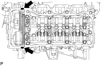 |
Apply seal packing as shown in the illustration.
| Seal Packing |
Install 3 new gaskets to the camshaft bearing cap.
Install a new gasket to the cylinder head cover sub-assembly LH.
Install a new seal washer to the bolt.
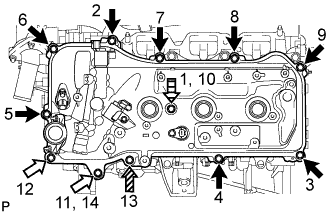 |
Temporarily install the cylinder head cover sub-assembly LH with the 12 bolts. Tighten the bolts uniformly in several steps.
| Bolt A |
| Bolt B |
| Bolt C |
| Bolt D |
| Item | Length |
| A | 25 mm (0.984 in.) |
| B | 35 mm (1.38 in.) |
| C | 70 mm (2.76 in.) |
| D | 60 mm (2.36 in.) |
| 8. CONNECT FUEL PIPE SUB-ASSEMBLY |
Connect the fuel pipe to the cylinder head cover sub-assembly LH with the 2 bolts.
| 9. INSTALL REAR CYLINDER HEAD COVER |
Temporarily install the cover with the 3 bolts.
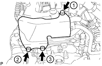 |
Tighten the 3 bolts in the sequence shown in the illustration.
| 10. INSTALL NO. 2 OIL PIPE |
Make sure that there is no foreign matter on the mesh of the oil control valve filter RH.
Install a new gasket and temporarily install the No. 2 oil pipe (on the cylinder head side) with the oil pipe union.
Install the oil control valve filter RH to the oil pipe union. Install new gaskets and temporarily install the oil pipe (on the head cover side).
Tighten the oil pipe union (on the cylinder head side).
Tighten the oil pipe union (on the head cover side).
| 11. INSTALL NO. 1 OIL PIPE |
Make sure that there is no foreign matter on the mesh of the oil control valve filter LH.
Install a new gasket and temporarily install the No. 1 oil pipe (on the cylinder head side) with the oil pipe union.
Install the oil control valve filter LH to the oil pipe union. Install new gaskets and temporarily install the oil pipe (on the head cover side).
Tighten the oil pipe union (on the cylinder head side).
Tighten the oil pipe union (on the head cover side).
| 12. INSTALL CRANKSHAFT PULLEY |
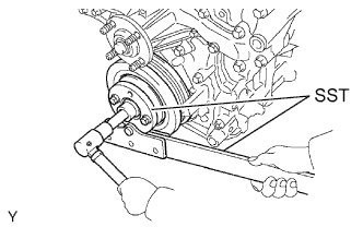 |
Using SST, install the crankshaft pulley to the crankshaft with the pulley set bolt.
| 13. INSTALL OIL FILTER BRACKET |
Install the oil filter bracket and new gasket to the oil pan sub-assembly with the 2 nuts and bolt.
| 14. INSTALL V-RIBBED BELT TENSIONER ASSEMBLY |
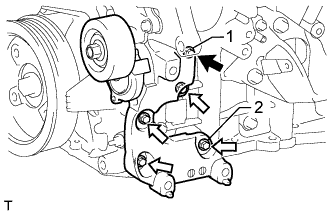 |
Temporarily install the V-ribbed belt tensioner assembly to the cylinder block sub-assembly and timing chain cover sub-assembly with the 5 bolts.
| Bolt A |
| Bolt B |
| Item | Length |
| A | 70 mm (2.76 in.) |
| B | 33 mm (1.30 in.) |
Tighten bolts 1 and 2 in numerical order.
Tighten the other bolts.
| 15. INSTALL NO. 2 IDLER PULLEY SUB-ASSEMBLY |
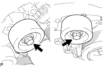 |
for Cover Separate Type:
Install the 2 idler pulley cover plates, 2 No. 2 idler pulley sub-assemblies and 2 No. 2 idler pulley cover plates to the timing chain cover sub-assembly with the 2 bolts.
for Cover Integrated Type:
Install the 2 No. 2 idler pulley sub-assemblies to the timing chain cover sub-assembly with the 2 bolts.
| 16. INSTALL NO. 1 IDLER PULLEY SUB-ASSEMBLY |
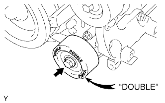 |
Install the No. 1 idler pulley sub-assembly to the timing chain cover sub-assembly with the bolt.
| 17. INSTALL NO. 3 WATER BY-PASS HOSE |
Install the No. 3 water by-pass hose to the No. 1 water outlet pipe.
| 18. INSTALL NO. 2 WATER BY-PASS HOSE |
Install the No. 2 water by-pass hose to the cylinder head LH.
| 19. INSTALL NO. 1 WATER BY-PASS HOSE |
Install the No. 1 water by-pass hose to the cylinder head sub-assembly.
| 20. INSTALL WATER INLET HOUSING |
Apply soapy water to a new O-ring, install it to the No. 1 water outlet pipe.
Install a new gasket to the water pump assembly.
Install the water inlet housing to the timing chain cover sub-assembly with the 5 bolts.
Connect the No. 1 water by-pass hose, No. 2 water by-pass hose and No. 3 water by-pass hose to the water inlet housing.
| 21. INSTALL ENGINE OIL LEVEL DIPSTICK GUIDE |
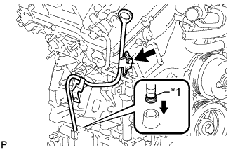 |
Install a new O-ring to the engine oil level dipstick guide.
| *1 | New O-Ring |
Apply a light coat of engine oil to the O-ring.
Push the engine oil level dipstick guide end into the guide hole.
Install the engine oil level dipstick guide to the timing chain cover sub-assembly with the bolt.
Install the engine oil level dipstick to the engine oil level dipstick guide.
| 22. INSTALL IGNITION COIL ASSEMBLY |
Install the 6 ignition coil assemblies to the cylinder head cover sub-assembly with the 6 bolts.
Connect the 6 ignition coil assembly connectors.
| 23. INSTALL NO. 2 EMISSION CONTROL VALVE SET (w/ Secondary Air Injection System) |
Install the No. 2 emission control valve set to the cylinder head cover sub-assembly LH with the 3 nuts.
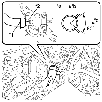 |
Connect the air hose assembly to the No. 2 emission control valve set with the hose clamp as shown in the illustration.
| *1 | Paint Mark of Air Hose Assembly |
| *2 | Protrusion of No. 2 Emission Control Valve Set |
| *a | View A |
| *b | Upper of Vehicle |
| *c | LH Side of Vehicle |
Connect the No. 2 emission control valve set connector.
| 24. INSTALL EMISSION CONTROL VALVE SET (w/ Secondary Air Injection System) |
Install the emission control valve set to the cylinder head cover sub-assembly with the 3 nuts.
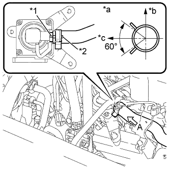 |
Connect the air hose assembly to the emission control valve set with the hose clamp as shown in the illustration.
| *1 | Protrusion of Emission Control Valve Set |
| *2 | Paint Mark of No. 1 Air Injection System Hose |
| *a | View A |
| *b | Upper of Vehicle |
| *c | RH Side of Vehicle |
Connect the emission control valve set connector.
| 25. INSTALL ENGINE ASSEMBLY |