 |
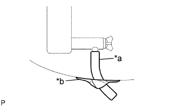
Install a vinyl hose to the radiator drain cock on the radiator assembly side.
| *a | Vinyl Hose |
| *b | Tape |
INTAKE MANIFOLD > REMOVAL |
| 1. DISCHARGE FUEL SYSTEM PRESSURE |
| 2. DRAIN ENGINE COOLANT |
Remove the service hole cover from the engine under cover.
|
Install a vinyl hose to the radiator drain cock on the radiator assembly side.
| *a | Vinyl Hose |
| *b | Tape |
Fix the vinyl hose with tape.
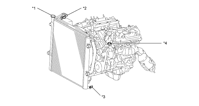
| *1 | Radiator Cap Sub-assembly | *2 | Radiator Reserve Tank Cap Sub-assembly |
| *3 | Radiator Drain Cock Plug | *4 | Cylinder Block Drain Cock Plug |
Loosen the radiator drain cock plug.
Remove the radiator cap sub-assembly and drain the engine coolant.
Loosen the cylinder block drain cock plug and drain the engine coolant from the engine.
| 3. REMOVE V-BANK COVER |
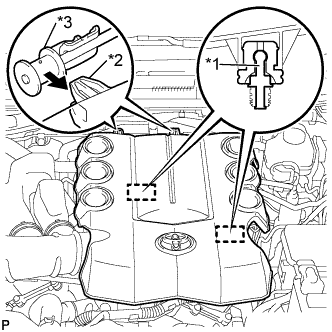 |
Raise the front of the V-bank cover to disengage the 2 pins.
| *1 | Pin |
| *2 | Hook |
| *3 | No. 1 V-bank Cover Bracket |
Disengage the 2 hooks and remove the V-bank cover from the No. 1 V-bank cover bracket.
| 4. REMOVE AIR CLEANER HOSE ASSEMBLY |
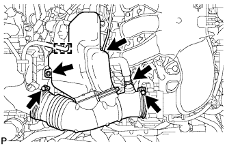 |
Loosen the hose clip and disconnect the ventilation hose from the air cleaner hose assembly.
Disconnect the vacuum hose from the air cleaner hose assembly.
Disengage the clamp and disconnect the wire harness from the air cleaner hose assembly.
Remove the bolt and disconnect the air cleaner hose assembly from the resonator bracket.
Loosen the 2 hose clamps and remove the air cleaner hose assembly from air cleaner cap sub-assembly and intake air surge tank.
| 5. DISCONNECT NO. 1 AIR INJECTION SYSTEM HOSE (w/ Secondary Air Injection System) |
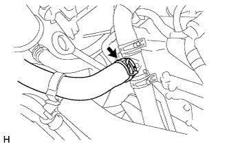 |
Loosen the hose clip and disconnect the No. 1 air injection system hose from the air hose assembly.
| 6. REMOVE AIR HOSE ASSEMBLY (w/ Secondary Air Injection System) |
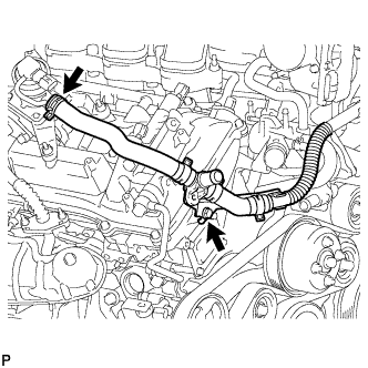 |
Remove the bolt and disconnect the air hose assembly from the timing chain cover sub-assembly.
Loosen the hose clip and disconnect the air hose assembly from the No. 1 emission control valve set.
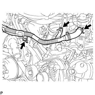 |
Remove the 2 bolts and disconnect the air hose assembly from the timing chain cover sub-assembly and No. 1 surge tank stay.
Loosen the hose clip and remove the air hose assembly from the No. 2 emission control valve set.
| 7. REMOVE INTAKE AIR SURGE TANK |
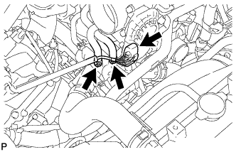 |
Disconnect the throttle with motor body assembly connector.
Loosen the 2 hose clips and disconnect the No. 4 water by-pass hose and No. 5 water by-pass hose from the water inlet housing.
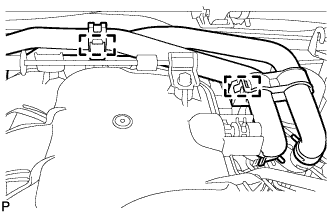 |
Disconnect the 2 clamps of the heater water hose from the intake air surge tank.
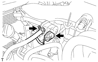 |
Loosen the hose clip and disconnect the No. 1 fuel vapor feed hose from the vacuum switching valve.
Disconnect the No. 1 vacuum switching valve connector.
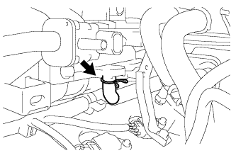 |
Loosen the hose clip and disconnect the No. 1 ventilation hose from the intake air surge tank.
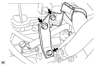 |
Remove the bolt and disconnect the wire harness clamp bracket from the No. 2 surge tank stay.
Remove the 2 bolts and No. 2 surge tank stay from the intake air surge tank.
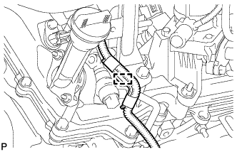 |
Disengage the clamp and disconnect the wire harness from the No. 1 surge tank stay.
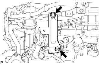 |
Remove the 2 bolts and No. 1 surge tank stay from the intake air surge tank.
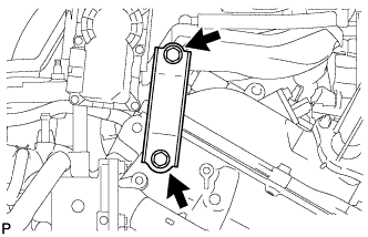 |
Remove the 2 bolts and throttle body bracket from the intake air surge tank.
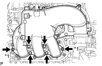 |
Using an 8 mm socket hexagon wrench, remove the 4 bolts, 2 nuts and intake air surge tank from the intake manifold.
| *1 | Nut |
Remove the air surge tank to intake manifold gasket from the intake air surge tank.
| 8. REMOVE REAR CYLINDER HEAD COVER |
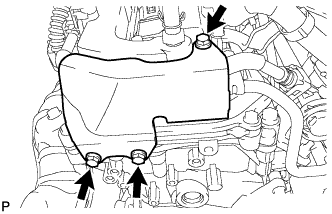 |
Remove the 3 bolts and cover.
| 9. DISCONNECT NO. 1 FUEL PIPE SUB-ASSEMBLY |
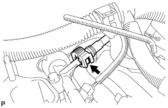 |
Disconnect the No. 1 fuel pipe sub-assembly (Click here).
| 10. DISCONNECT NO. 2 FUEL PIPE SUB-ASSEMBLY |
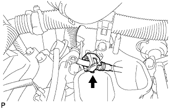 |
Disconnect the No. 2 fuel pipe sub-assembly (Click here).
| 11. REMOVE FUEL DELIVERY PIPE SUB-ASSEMBLY |
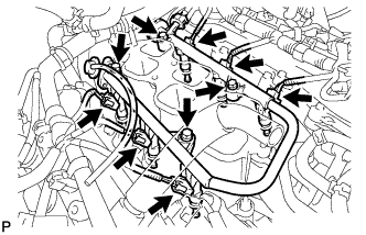 |
Disconnect the 6 fuel injector connectors.
Remove the 4 bolts and fuel delivery pipe together with the 6 fuel injectors.
| 12. REMOVE INTAKE MANIFOLD |
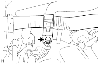 |
Remove the bolt and the wire harness clamp bracket from the intake manifold.
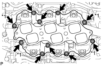 |
Remove the 4 nuts, 6 bolts and intake manifold from the cylinder head sub-assembly.
| *1 | Nut |
Remove the No. 1 intake manifold to head gasket and No. 2 intake manifold to head gasket from the cylinder head sub-assembly.
| 13. REMOVE STUD BOLT |
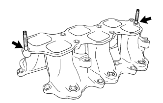 |
Using "Torx" socket wrench E8, remove the 2 stud bolts from the intake manifold.