 |
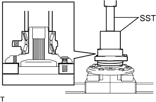
Using SST and a press, install a new front axle hub bearing.
- SST
- 09649-17010
09950-70010 (09951-07100)
- NOTICE:
- Be careful not to damage the hub bearing.
FRONT AXLE HUB > INSTALLATION |
| 1. INSTALL FRONT AXLE HUB BEARING |
|
Using SST and a press, install a new front axle hub bearing.
| 2. INSTALL FRONT DISC |
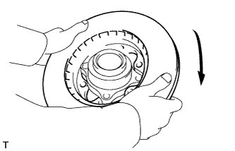 |
Install the front disc as shown in the illustration.
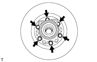 |
Install the front disc with the 6 bolts.
| 3. INSTALL FRONT WHEEL ADJUSTING NUT (w/ ABS) |
Hold the front axle assembly in a vise between aluminium plates.
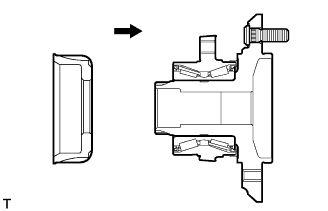 |
Install the skid control rotor as shown in the illustration.
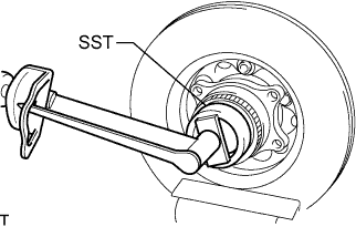 |
Using SST, install the front wheel adjusting nut.
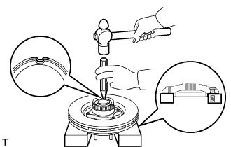 |
Using a chisel and hammer, stake the front wheel adjusting nut.
| 4. INSTALL FRONT WHEEL ADJUSTING NUT (w/o ABS) |
Hold the front axle assembly in a vise between aluminium plates.
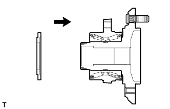 |
Install the front wheel bearing dust deflector as shown in the illustration.
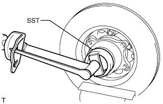 |
Using SST, install the front wheel adjusting nut.
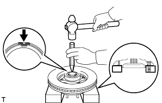 |
Using a chisel and hammer, stake the front wheel adjusting nut.
| 5. INSTALL FRONT LOWER BALL JOINT ASSEMBLY |
Fix the steering knuckle in the vise using aluminium plates.
Install the front lower ball joint assembly to the steering knuckle with the nut.
Install a new cotter pin to the front lower ball joint assembly.
| 6. INSTALL STEERING KNUCKLE |
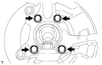 |
Install the steering knuckle and brake dust cover to the front axle hub sub-assembly with the 4 bolts.
| 7. INSTALL FRONT AXLE ASSEMBLY |
Temporarily install the front axle assembly to the front suspension upper arm and front suspension lower arm.
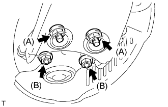 |
Fully tighten front suspension lower arm with the 4 bolts and 4 nuts.
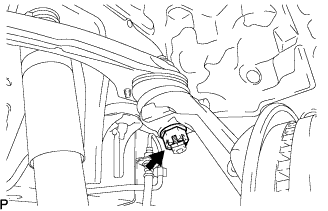 |
Fully tighten the front suspension upper arm with the nut.
Install a new cotter pin to the front suspension upper arm.
| 8. INSTALL TIE ROD END SUB-ASSEMBLY |
Install the tie rod end sub-assembly to the steering knuckle with the castle nut.
Install a new cotter pin to the tie rod end sub-assembly.
| 9. INSTALL FRONT DISC BRAKE CALIPER ASSEMBLY |
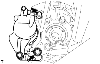 |
Install the brake caliper assembly to the steering knuckle with the 2 bolts.
| 10. INSTALL FRONT SPEED SENSOR (w/ ABS) |
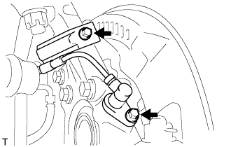 |
Install the speed sensor to the steering knuckle with the 2 bolts.
| 11. INSPECT FRONT AXLE HUB BEARING LOOSENESS |
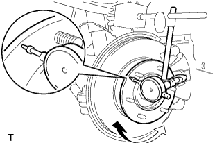 |
Using a dial indicator, check for looseness near the center of the axle hub.
| 12. INSPECT FRONT AXLE HUB RUNOUT |
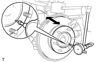 |
Using a dial indicator, check for runout on the surface of the axle hub outside the hub bolt.
| 13. INSTALL FRONT WHEEL |
| 14. INSPECT WHEEL ALIGNMENT |
| 15. CHECK ABS SPEED SENSOR SIGNAL |