 |
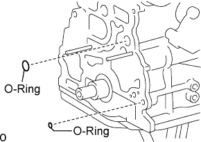
Install 2 new O-rings to the cylinder block grooves.
OIL PUMP > INSTALLATION |
| 1. INSTALL TIMING GEAR CASE ASSEMBLY |
|
Install 2 new O-rings to the cylinder block grooves.
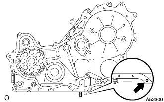 |
Install the stud bolt.
Remove any old packing (FIPG) material.
Install the oil pump rotor to the timing gear case.
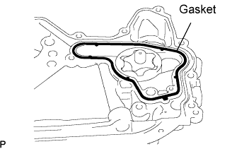 |
Install a new gasket to the groove of the timing gear case.
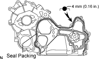 |
Apply seal packing to the timing gear case as shown in the illustration.
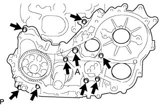 |
Install the timing gear case with the union bolt and 8 bolts.
Remove the screw plug.
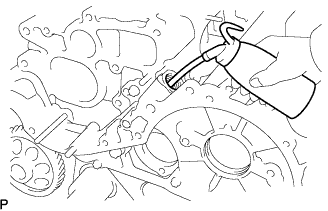 |
Pour approximately 50 cc (1.7 fl.oz) of engine oil into the oil pump.
Reinstall a new gasket and the screw plug.
| 2. INSTALL OIL STRAINER SUB-ASSEMBLY |
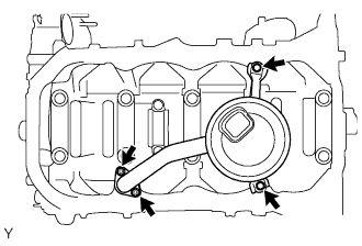 |
Install a new gasket and the oil strainer with the 2 bolts and 2 nuts.
| 3. INSTALL OIL PAN SUB-ASSEMBLY |
Remove any old packing (FIPG) material.
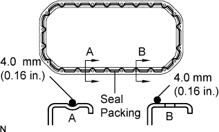 |
Apply seal packing to the oil pan as shown in the illustration.
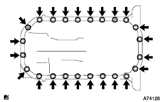 |
Install the oil pan with the 22 bolts and 2 nuts.
Install a new gasket and the drain plug.
| 4. INSTALL SUPPLY PUMP GEAR |
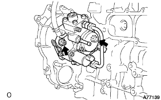 |
Install the supply pump with the 2 nuts.
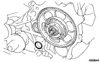 |
Temporarily install the O-ring and supply pump gear with the nut.
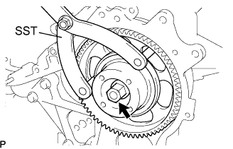 |
Using SST, tighten the nut.
| 5. INSTALL CRANKSHAFT TIMING GEAR |
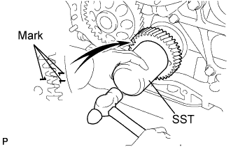 |
Face the crankshaft timing gear with timing mark 1 facing forward.
Align the set key on the crankshaft with the key groove of the crankshaft timing gear.
Using SST and a hammer, tap in the timing gear.
| 6. INSTALL IDLE GEAR SHAFT NO.1 |
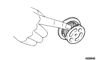 |
Coat the idle gear shaft No.1 with engine oil as shown in the illustration.
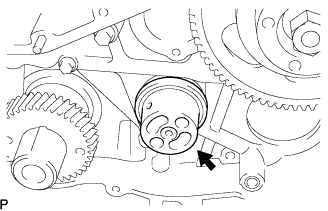 |
Install the gear shaft.
| 7. INSTALL IDLE GEAR NO.1 |
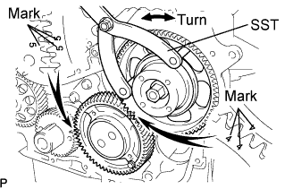 |
Align the "5" timing marks of the idle gear and crankshaft timing gear.
Using SST, turn the supply pump gear, and align the "4" timing marks of the idle gear and supply pump gear, and mesh the gears.
| 8. INSTALL CRANKSHAFT POSITION SENSOR PLATE NO.1 |
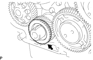 |
Align the set key with the key groove of the sensor plate.
Install the sensor plate with the cup side facing outward.
| 9. INSTALL IDLE GEAR THRUST PLATE |
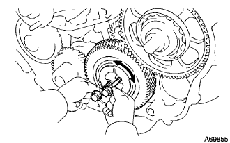 |
Face the thrust plate with the protrusion facing outward.
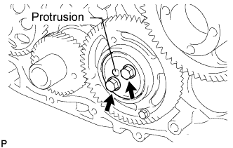 |
Align the bolt holes, and install the thrust plate with the 2 bolts.
| 10. INSTALL TIMING CHAIN OR BELT COVER OIL SEAL |
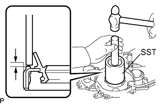 |
Using SST and a hammer, tap in a new oil seal until its surface is flush with the timing gear cover edge.
Apply MP grease to the oil seal lip.
| 11. INSTALL TIMING GEAR CASE OR TIMING CHAIN CASE OIL SEAL |
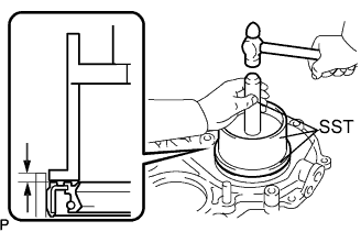 |
Using SST and a hammer, tap in a new oil seal until its surface is flush with the timing gear cover edge.
Apply MP grease to the oil seal lip.
| 12. INSTALL TIMING GEAR CASE |
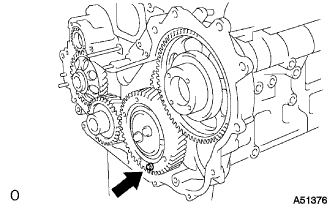 |
Remove the service bolt.
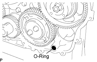 |
Install a new O-ring to the timing gear case assembly.
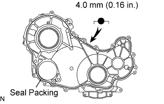 |
Apply seal packing to the timing gear case as shown in the illustration.
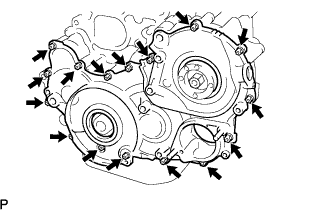 |
Install the timing gear case with the 14 bolts and 2 nuts.
| 13. INSTALL WATER PUMP ASSEMBLY |
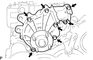 |
Install a new gasket and the water pump with the 5 bolts and 2 nuts.
| 14. INSTALL TIMING BELT NO.2 COVER |
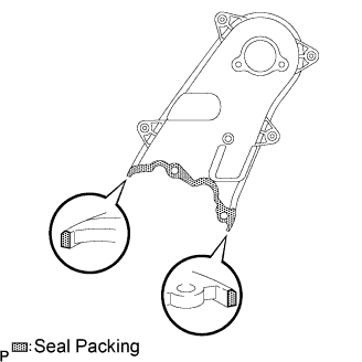 |
Apply seal packing to the timing gear cover as shown in the illustration.
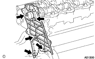 |
Install the timing belt No. 2 cover with the 4 bolts and nut.
| 15. INSTALL CAMSHAFT TIMING PULLEY |
Install the set key to the key groove of the camshaft.
Align the set key with the key groove of the timing pulley.
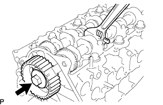 |
Hold the hexagon portion of the camshaft, and install the timing pulley with the bolt.
| 16. INSTALL CYLINDER HEAD COVER SUB-ASSEMBLY |
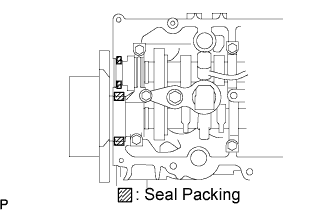 |
Apply seal packing to the cylinder head as shown in the illustration.
Install a new gasket to the cylinder head cover.
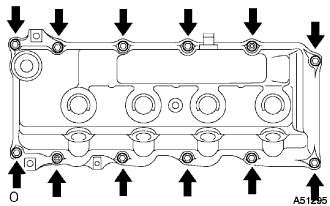 |
Install the cylinder head cover with 10 bolts and 2 nuts. Uniformly tighten the bolts and nuts in several steps.
| 17. INSTALL NOZZLE HOLDER SEAL |
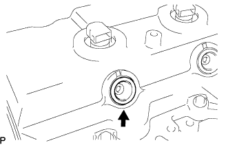 |
Install 4 new holder seals.
| 18. INSTALL OIL FILLER CAP SUB-ASSEMBLY |
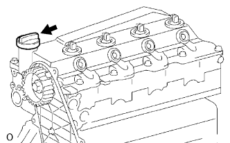 |
Install the oil filler cap.
| 19. INSTALL ENGINE OIL LEVEL SENSOR |
Set a new gasket, and then install the engine oil level sensor with the 4 bolts.
| 20. INSTALL CRANKSHAFT POSITION SENSOR |
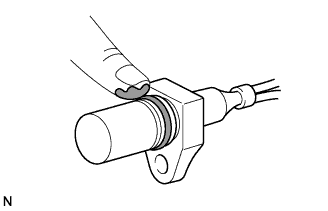 |
Apply a light coat of engine oil to the O-ring of the crankshaft position sensor.
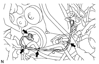 |
Install the crankshaft position sensor with the bolt.
Connect the 3 wire harness clamps.
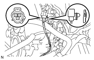 |
Connect the crankshaft position sensor connector to the vacuum pipe No.1.
Connect the crankshaft position sensor connector.
| 21. INSTALL CAMSHAFT POSITION SENSOR |
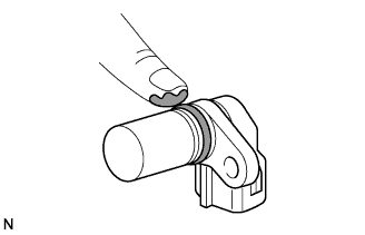 |
Apply a light coat of engine oil to the O-ring of the camshaft position sensor.
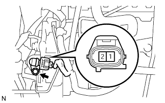 |
Install the camshaft position sensor with the bolt.
Connect the camshaft position sensor connector.
| 22. INSTALL VACUUM PUMP ASSEMBLY |
Apply the engine oil to the 2 new O-rings.
Install the 2 O-rings to the vacuum pump assembly.
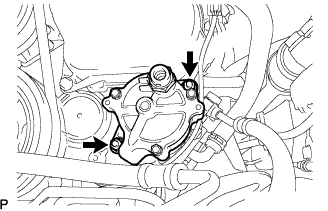 |
Install the vacuum pump assembly to the engine with the 2 nuts.
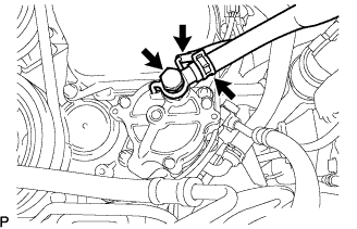 |
Install the vacuum pump union and the 2 new gaskets with the union bolt.
Connect the 2 hoses with the clip to the vacuum pump.
| 23. INSTALL CRANKSHAFT PULLEY |
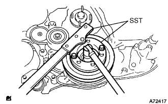 |
Tighten the bolt holding the crankshaft pulley with SST.
| 24. INSTALL TIMING BELT IDLER SUB-ASSEMBLY NO.1. |
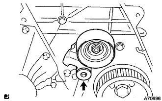 |
Using a 10 mm socket hexagon wrench, install the timing belt idler No.1 and plate washer with the bolt.
| 25. INSTALL V-RIBBED BELT TENSIONER ASSEMBLY |
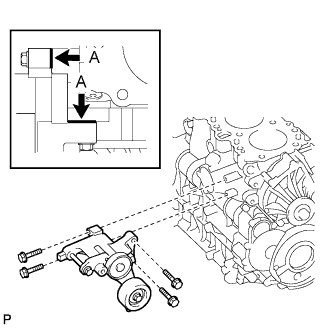 |
Temporarily install the V-ribbed belt tensioner with the 4 bolts.
Tighten the V-ribbed belt tensioner with the 4 bolts.
| 26. INSTALL GENERATOR ASSEMBLY |
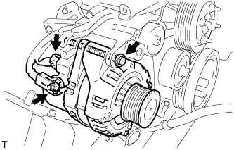 |
Install the generator assembly with the bolt.
Install the generator wire to terminal B with the nut.
Install the terminal cap.
Connect the generator connector.
| 27. INSTALL GENERATOR BRACKET |
Install the generator bracket with the bolt.
| 28. INSTALL IDLE PULLEY ASSEMBLY |
Install the idler pulley and washers with the bolt.
| 29. INSTALL COMPRESSOR BRACKET |
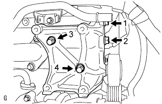 |
Temporarily install the compressor bracket with the 4 bolts.
Install the compressor bracket by tightening the 4 bolts as shown in the illustration.
| 30. INSTALL PUMP DRIVE SHAFT PULLEY |
| 31. CHECK PUMP DRIVE SHAFT THRUST CLEARANCE |
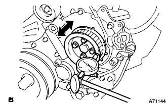 |
Push the pump drive shaft pulley back and forth to check a thrust clearance of the injection pump drive shaft.
| 32. INSTALL COMMON RAIL ASSEMBLY |
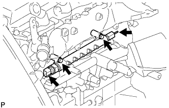 |
Install the common rail assembly with the 2 bolts.
Connect the fuel hose to the fuel pressure limiter.
Connect the fuel pressure sensor connector.
| 33. INSTALL FUEL INLET PIPE SUB-ASSEMBLY |
Temporarily install the fuel inlet pipe.
Using SST, tighten the injection pipe on the common rail side.
Using SST, tighten the injection pipe on the supply pump side.
| 34. INSTALL INJECTION PIPE |
Install the injection pipes.
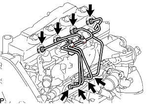 |
Temporarily install the 4 injection pipes.
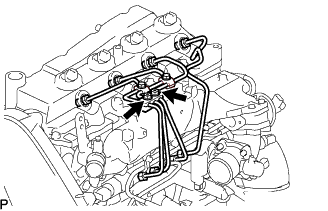 |
Install the injection pipe clamp No.3 in 2 nuts.
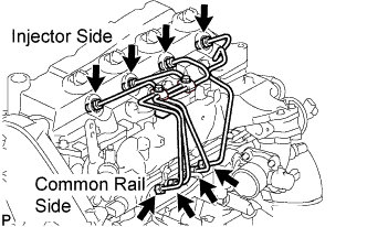 |
Fasten the union sequentially, from the injection pipe common rail to the injector, using SST.
| 35. INSTALL OIL LEVEL GAGE GUIDE |
Install a new O-ring to the oil level gauge guide.
Apply a light coat of engine oil to the O-ring.
Install the oil level gauge guide with the bolt.
Install the oil level gauge.
| 36. INSTALL EGR PIPE SUB-ASSEMBLY NO.1 |
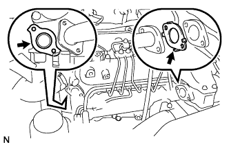 |
Install 2 new gaskets to the cylinder head and the EGR pipe sub-assembly No.1 as shown in the illustration.
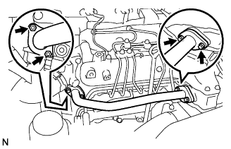 |
Install the EGR pipe with the 2 bolts and the 2 nuts.
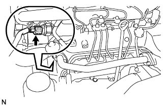 |
Connect the fuel pressure sensor connector.
| 37. INSTALL FAN PULLEY |
Install the fan pulley with the 4 nuts.
| 38. PERFORM PISTON AND VALVE BREAK PREVENT WORK |
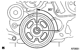 |
When turning the camshaft with the timing belt removed, turn the crankshaft 90° counterclockwise.
| 39. INSTALL TIMING BELT |
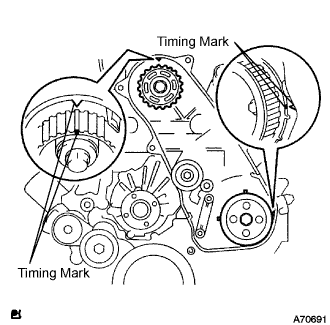 |
Check that the timing marks are aligned as shown in the illustration.
Install the timing belt to pump drive shaft pulley, camshaft timing pulley and timing belt idler No.1 in sequence.
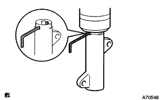 |
Set the tensioner to the press upright.
Using a press, slowly apply 981 to 9,807 N (100 to 1,000 kgf, 220 to 2,205 lbf) of force to the push rod.
Align the holes of push rod and housing, pass a 1.27 mm hexagon wrench through the holes to keep the setting position of the push rod.
Temporarily install the timing belt tensioner with the 2 bolts while pushing the idler pulley toward the timing belt.
Tighten the 2 bolts.
Remove the 1.5 mm hexagon wrench from the tensioner.
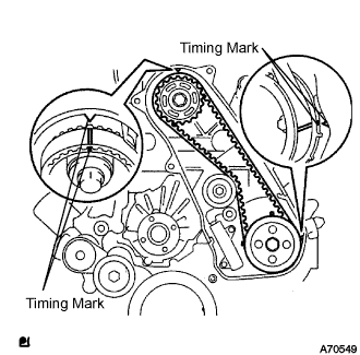 |
Turn the crankshaft in the clockwise direction twice, check that the timing marks are aligned as shown in the illustration.
| 40. INSTALL TIMING BELT NO.1 COVER |
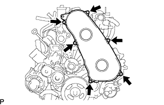 |
Install the timing belt No.1 cover with the 6 bolts.
Install the wire harness clamp.
| 41. INSTALL VANE PUMP ASSEMBLY |
Install a new vane pump O-ring to the vane pump assembly.
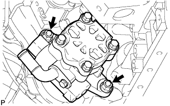 |
Install the vane pump assembly with the 2 nuts.
| 42. INSTALL ENGINE ASSEMBLY |