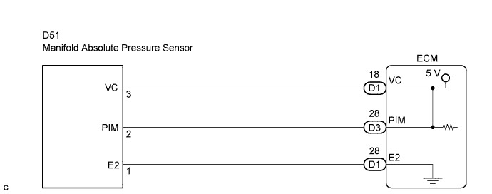
DTC P0105/31 Manifold Absolute Pressure / Barometric Pressure Circuit |
DTC P0107/35 Manifold Absolute Pressure / Barometric Pressure Circuit Low Input |
DTC P0108/35 Manifold Absolute Pressure / Barometric Pressure Circuit High Input |
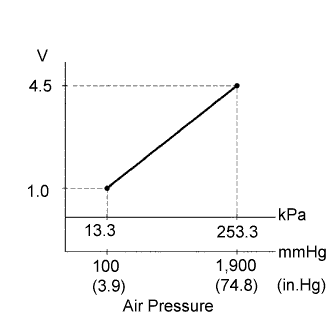
| DTC No. | DTC Detection Condition | Trouble Area |
| P0105/35 P0107/35 P0108/35 | Open or short in manifold absolute pressure sensor circuit for 0.5 seconds or more (1 trip detection logic) |
|
| Intake Manifold Pressure | Malfunction |
| Approximately 0 kPa | Short in PIM circuit |
| 250 kPa (1,875 mmHg, 73.8 in.Hg) or more |
|
| 1.READ VALUE OF MANIFOLD ABSOLUTE PRESSURE SENSOR |
Connect the intelligent tester to the DLC3.
Turn the ignition switch ON and turn the intelligent tester ON.
Enter the following menus: Powertrain / ECD / Data List / MAP.
Read the values.
|
| ||||
| NG | |
 |
| 2.CHECK ECM TERMINAL VOLTAGE (VC TERMINAL) |
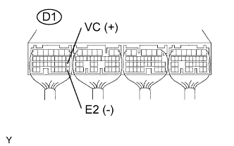 |
Turn the ignition switch ON.
Measure the voltage of the ECM connector.
| Tester Connection | Specified Condition |
| D1-18 (VC) - D1-28 (E2) | 4.5 to 5.5 V |
|
| ||||
| OK | |
|
| 3.CHECK MANIFOLD ABSOLUTE PRESSURE SENSOR |
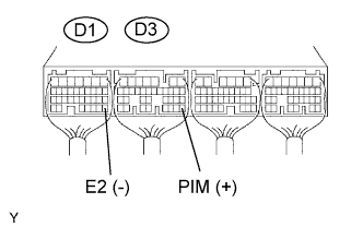 |
Turn the ignition switch ON.
Apply pressure to the manifold absolute pressure sensor. (Click here)
Measure the voltage of the ECM connectors.
| Tester Connection | Condition | Specified Condition |
| D3-28 (PIM) - D1-28 (E2) | Applied negative pressure of 40 kPa (300 mmHg, 11.8 in.Hg) | 1.3 to 1.9 V |
| D3-28 (PIM) - D1-28 (E2) | Same as atmospheric pressure | 2.4 to 3.1 V |
| D3-28 (PIM) - D1-28 (E2) | Applied positive pressure of 170 kPa (1,275 mmHg, 50.2 in.Hg) | 3.7 to 4.3 V |
|
| ||||
| NG | |
|
| 4.CHECK HARNESS AND CONNECTOR (MANIFOLD ABSOLUTE PRESSURE SENSOR - ECM) |
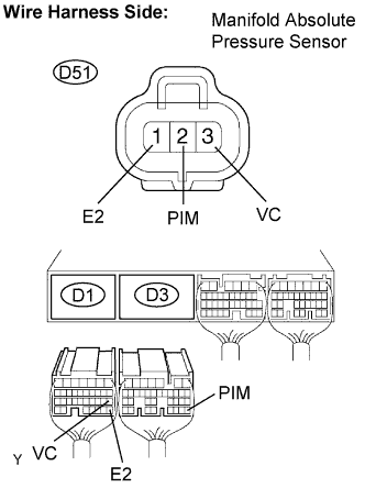 |
Disconnect the D51 sensor connector.
Disconnect the D3 and D1 ECM connectors.
Measure the resistance of the wire harness side connectors.
| Tester Connection | Specified Condition |
| D51-2 (PIM) - D3-28 (PIM) | Below 1 Ω |
| D51-3 (VC) - D1-18 (VC) | Below 1 Ω |
| D51-1 (E2) - D1-28 (E2) | Below 1 Ω |
| D51-2 (PIM) or D3-28 (PIM) - Body ground | 10 kΩ or higher |
| D51-3 (VC) or D1-18 (VC) - Body ground | 10 kΩ or higher |
| D51-1 (E2) or D1-28 (E2) - Body ground | 10 kΩ or higher |
|
| ||||
| OK | |
|
| 5.INSPECT TURBOCHARGER SUB-ASSEMBLY |
Check the turbocharger sub-assembly. (Click here)
|
| ||||
| OK | |
|
| 6.INSPECT EGR VALVE ASSEMBLY |
Check the EGR valve assembly. (Click here)
|
| ||||
| OK | ||
 | ||
| ||
| 1.CHECK ECM TERMINAL VOLTAGE (VC TERMINAL) |
|
Turn the ignition switch ON.
Measure the voltage of the ECM connector.
| Tester Connection | Specified Condition |
| D1-18 (VC) - D1-28 (E2) | 4.5 to 5.5 V |
|
| ||||
| OK | |
|
| 2.CHECK MANIFOLD ABSOLUTE PRESSURE SENSOR |
|
Turn the ignition switch ON.
Apply pressure to the manifold absolute pressure sensor. (Click here )
Measure the voltage of the ECM connectors.
| Tester Connection | Condition | Specified Condition |
| D3-28 (PIM) - D1-28 (E2) | Applied negative pressure of 40 kPa (300 mmHg, 11.8 in.Hg) | 1.3 to 1.9 V |
| D3-28 (PIM) - D1-28 (E2) | Same as atmospheric pressure | 2.4 to 3.1 V |
| D3-28 (PIM) - D1-28 (E2) | Applied positive pressure of 170 kPa (1,275 mmHg, 50.2 in.Hg) | 3.7 to 4.3 V |
|
| ||||
| NG | |
|
| 3.CHECK HARNESS AND CONNECTOR (MANIFOLD ABSOLUTE PRESSURE SENSOR - ECM) |
|
Disconnect the D51 sensor connector.
Disconnect the D3 and D1 ECM connectors.
Measure the resistance of the wire harness side connectors.
| Tester Connection | Specified Condition |
| D51-2 (PIM) - D3-28 (PIM) | Below 1 Ω |
| D51-3 (VC) - D1-18 (VC) | Below 1 Ω |
| D51-1 (E2) - D1-28 (E2) | Below 1 Ω |
| D51-2 (PIM) or D3-28 (PIM) - Body ground | 10 kΩ or higher |
| D51-3 (VC) or D1-18 (VC) - Body ground | 10 kΩ or higher |
| D51-1 (E2) or D1-28 (E2) - Body ground | 10 kΩ or higher |
|
| ||||
| OK | |
|
| 4.INSPECT TURBOCHARGER SUB-ASSEMBLY |
Check the turbocharger sub-assembly. (Click here)
|
| ||||
| OK | |
|
| 5.INSPECT EGR VALVE ASSEMBLY |
Check the EGR valve assembly. (Click here)
|
| ||||
| OK | ||
| ||
| ||
