 |
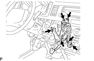
Using the 5 bolts and nut, temporarily install the brake pedal support assembly to the dash panel.
BRAKE PEDAL > INSTALLATION |
| 1. TEMPORARILY TIGHTEN BRAKE PEDAL SUPPORT ASSEMBLY |
|
Using the 5 bolts and nut, temporarily install the brake pedal support assembly to the dash panel.
| 2. INSTALL ACCELERATOR PEDAL ROD ASSEMBLY |
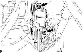 |
Install the accelerator pedal rod assembly with the 2 nuts.
| 3. CONNECT WIRE HARNESS |
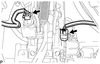 |
Connect the 2 connectors.
| 4. INSTALL BRAKE BOOSTER GASKET |
| 5. INSTALL BRAKE BOOSTER ASSEMBLY |
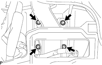 |
Install the brake booster assembly with the 4 nuts.
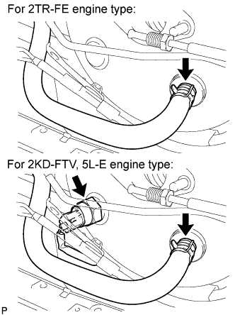 |
Connect the vacuum hose with the clip.
Fro 2KD-FTV, 5L-E engine type:
Connect the vacuum warning switch connector to the brake booster assembly.
| 6. FULLY TIGHTEN BRAKE PEDAL SUPPORT ASSEMBLY |
|
Fully tighten the 5 bolts and nut.
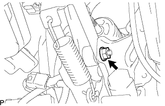 |
Fully tighten the nut.
| 7. INSTALL BRAKE TUBE |
Automatic transmission:
Connect the 2 tubes to the clamp.
Manual transmission:
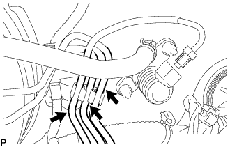 |
Connect the 3 tubes to the clamp.
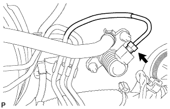 |
Using SST, connect the clutch tube to the clutch master cylinder.
| 8. INSTALL MASTER CYLINDER PUSH ROD CLEVIS |
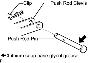 |
Apply lithium soap base glycol grease to the clevis pin.
Install the push rod clevis to the brake pedal support assembly with the clevis pin and a new clip.
| 9. INSTALL INSTRUMENT PANEL FINISH PANEL LOWER |
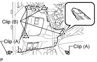 |
Engage the 4 clips (B).
Install the instrument panel finish panel lower with the 2 clips (A).
| 10. INSTALL HEADLIGHT ASSEMBLY LH (RHD (NARROW BODY TYPE)) |
| 11. INSTALL HEADLIGHT ASSEMBLY RH (RHD (WIDE BODY TYPE)) |
| 12. INSTALL AIR INLET DUCT NO.2 (LHD (W/ INTERCOOLER ASSEMBLY)) |
| 13. INSTALL AIR INLET DUCT NO.1 (LHD (W/ INTERCOOLER ASSEMBLY)) |
| 14. INSTALL RADIATOR SUPPORT SEAL UPPER (LHD (W/O INTERCOOLER ASSEMBLY)) |
| 15. INSTALL FRONT BUMPER SIDE SUPPORT RH (RHD (BODY TYPE WIDE)) |
| 16. INSTALL FRONT BUMPER COVER (RHD (BODY TYPE WIDE)) |
| 17. INSTALL STEP PLATE COVER RH (RHD (BODY TYPE WIDE)) |
| 18. INSTALL STEP PLATE COVER LH (RHD (BODY TYPE WIDE)) |
| 19. INSTALL RADIATOR GRILLE (W/O INTERCOOLER ASSEMBLY) |
| 20. INSTALL BRAKE MASTER CYLINDER |
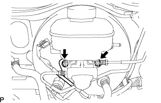 |
Install the brake master cylinder and harness clamp bracket to the booster with the 2 nuts.
Manual Transmission:
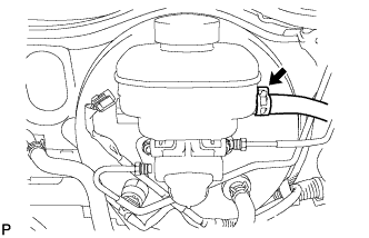 |
Install the clutch reservoir tube with the clip.
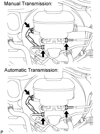 |
Using SST, connect the 2 brake tubes to the master cylinder.
Connect the level warning light switch connector.
| 21. ADD BRAKE FLUID |
| 22. BLEED BRAKE MASTER CYLINDER |
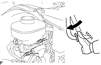 |
Using SST, disconnect the brake lines from the master cylinder.
Slowly depress the brake pedal and hold it there.
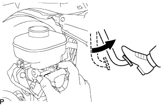 |
Block the outer holes with your fingers, and release the brake pedal.
Remove your fingers. Slowly depress the brake pedal and hold it again. Block the outer holes with your fingers and release the brake pedal. Repeat this procedure 3 or 4 times.
Using SST, connect the brake lines to the master cylinder.
| 23. BLEED BRAKE LINE |
Connect the vinyl tube to the bleeder plug.
Depress the brake pedal several times and loosen the bleeder plug with the pedal held down.
At the point where the fluid stops coming out, tighten the bleeder plug and release the brake pedal.
Repeat this procedure until the air in the brake fluid is completely bled out.
Tighten the bleeder plug.
Front bleeder plug:
Rear bleeder plug:
Repeat the above procedure to bleed the air out of the brake line for each wheel.
| 24. INSPECT BRAKE FLUID LEVEL |
Check the fluid level and add fluid if necessary.
| 25. INSPECT BRAKE FLUID |
| 26. VEHICLE PREPARATION FOR HEADLIGHT AIM ADJUSTMENT |
Prepare the vehicle:
| 27. PREPARATION FOR HEADLIGHT AIMING (USING A SCREEN) |
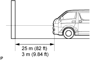 |
Prepare the vehicle according to the following conditions:
Prepare a piece of thick white paper (approximately 2 m (6.6 ft) (height) x 4 m (13.1 ft) (width)) to use as a screen.
Draw a vertical line down the center of the screen (V line).
Set the screen as shown in the illustration.
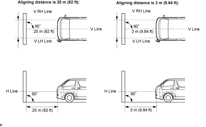
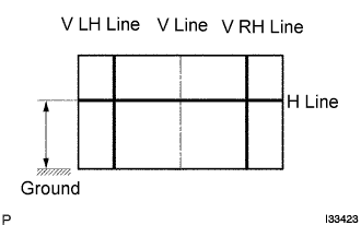 |
Draw base lines (H line, V LH, V RH lines) on the screen as shown in the illustration.
H Line (Headlight height):
V LH Line, V RH Line (Center mark position of left-hand (LH) and right-hand (RH) headlights):
| 28. HEADLIGHT AIMING INSPECTION |
Cover or disconnect the connector of the headlight on the opposite side to prevent light from the headlight not being inspected from affecting headlight aiming inspection.
Start the engine.
With headlight leveling switch:
Set the headlight leveling switch to 0 (zero).
Turn on the headlight and make sure that the cutoff line falls within the specified area, as shown in the illustration.
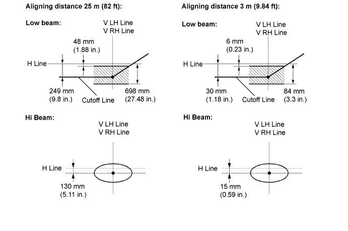
| 29. ADJUST HEADLIGHT AIMING |
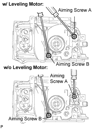 |
Adjust the aim vertically:
Adjust the aim horizontally:
| 30. INSPECT BRAKE PEDAL HEIGHT |
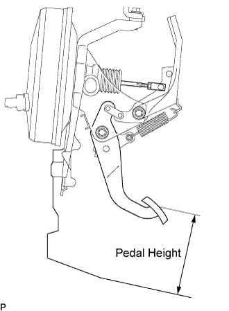 |
Check brake pedal height.
| 31. ADJUST BRAKE PEDAL HEIGHT |
Disconnect the stop light switch connector.
Turn the stop light switch assembly counter-clockwise and remove it.
Remove the brake booster (Click here).
Loosen the push rod lock nut.
Adjust the pedal height by turning the pedal push rod clevis.
Tighten the push rod lock nut.
Install the brake booster (Click here).
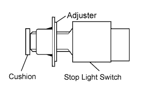 |
Insert the stop light switch into the adjuster until it slightly touches the cushion.
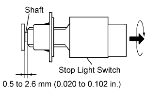 |
Turn the stop light switch assembly clockwise by approximately 90°.
Connect the stop light switch connector.
Check the clearance of the shaft.
| 32. INSPECT BRAKE PEDAL FREE PLAY |
Stop the engine and depress the brake pedal several times until there is no more vacuum left in the booster.
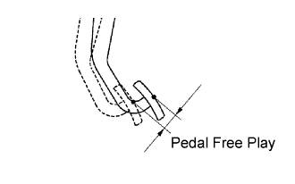 |
Push in the pedal until the beginning of the resistance is felt. Measure the distance as shown in the illustration.
| 33. INSPECT BRAKE PEDAL RESERVE DISTANCE |
Stop the engine and depress the brake pedal several times until there is no more vacuum left in the booster.
Release the parking brake handle.
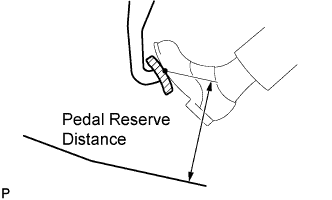 |
With the engine running, depress the pedal and measure the pedal reserve distance as shown in the illustration.