 |
Connect the connector.
RADIO ANTENNA CORD > INSTALLATION |
| 1. INSTALL RADIO ANTENNA CORD |
|
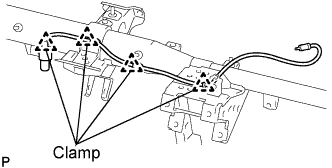
Connect the connector.
Install the 4 clamps and the radio antenna cord.
| 2. INSTALL INSTRUMENT PANEL ASSEMBLY |
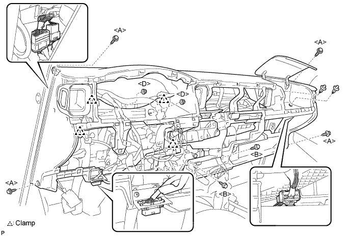
Connect the all connectors.
Install the instrument panel assembly with the 4 bolts <A>, 2 screws <B> and 2 nuts <D>.
| 3. INSTALL FRONT PILLAR GARNISH RH |
| 4. INSTALL FRONT PILLAR GARNISH LH |
| 5. INSTALL ASSIST GRIP ASSEMBLY |
| 6. INSTALL ASSIST GRIP PLUG |
| 7. INSTALL HAZARD WARNING SIGNAL SWITCH ASSEMBLY |
| 8. INSTALL FRONT PASSENGER AIRBAG ASSEMBLY |
Engage the clamps and claws, and install the front passenger airbag assembly.
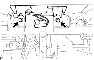 |
Install the instrument panel passenger airbag with the 2 bolts.
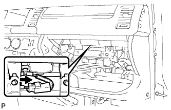 |
Connect the airbag connector.
Install the airbag connector to the reinforcement.
| 9. INSTALL AIR CONDITIONER PANEL SUB-ASSEMBLY |
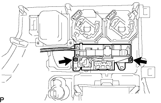 |
Install the heater control base with the 2 screws.
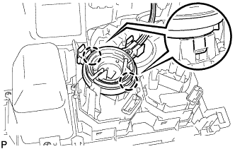 |
Engage the 2 claws to install the defroster damper control cable sub-assembly.
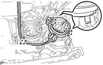 |
Engage the 2 claws to install the boost ventilator control cable sub-assembly.
Install the clamp.
Install the connector.
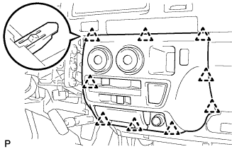 |
Engage the 9 clips to install the air conditioner panel sub-assembly.
| 10. INSTALL SHIFT LOCK CONTROL UNIT ASSEMBLY |
| 11. INSTALL FLOOR SHIFT SHIFT LEVER ASSEMBLY |
| 12. INSTALL GLOVE COMPARTMENT DOOR ASSEMBLY |
| 13. INSTALL INSTRUMENT PANEL FINISH PANEL LOWER CENTER |
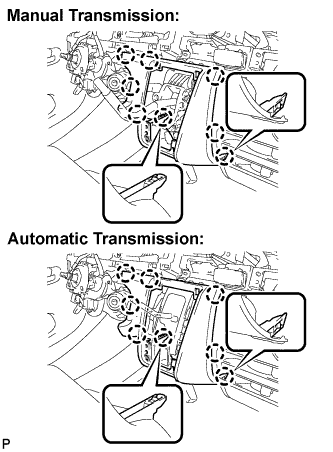 |
Engage the 8 claws and install the instrument panel finish panel lower center.
| 14. INSTALL SHIFTING HOLE COVER ASSEMBLY |
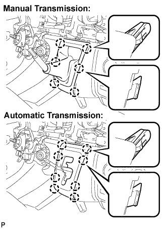 |
Manual Transmission:
Engage the 6 claws and install the shifting hole cover assembly.
Automatic Transmission:
Engage the 8 claws and install the sifting hole cover assembly.
| 15. INSTALL SHIFT LEVER KNOB |
| 16. INSTALL PARKING BRAKE HOLE COVER |
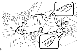 |
Engage the 6 claws and install the parking brake hole cover.
| 17. INSTALL INSTRUMENT PANEL UNDER COVER SUB-ASSEMBLY NO.1 |
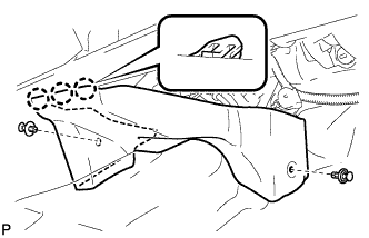 |
Engage the 3 claws.
Install the instrument panel No.1 under cover sub-assembly with the 2 clips.
| 18. INSTALL INSTRUMENT PANEL FINISH PANEL LOWER |
| 19. INSTALL RADIO RECEIVER ASSEMBLY |
| 20. INSTALL STEREO OPENING COVER |
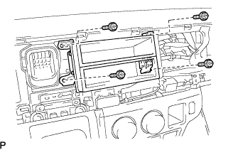 |
Install the radio tuner opening cover with bracket with the 4 screws <C>.
| 21. INSTALL INSTRUMENT PANEL CUP HOLDER ASSEMBLY |
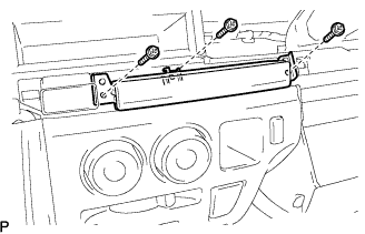 |
Install the instrument panel cup holder assembly with the 3 screws <C>.
| 22. INSTALL COMBINATION METER ASSEMBLY |
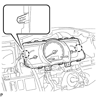 |
Connect the connector and engage the 2 claws.
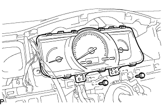 |
Install the combination meter assembly with the 2 screws.
| 23. INSTALL INSTRUMENT CLUSTER FINISH PANEL SUB-ASSEMBLY |
| 24. INSTALL INSTRUMENT CLUSTER FINISH PANEL ASSEMBLY |
| 25. INSTALL INSTRUMENT CLUSTER FINISH PANEL GARNISH NO.1 |
| 26. INSTALL INSTRUMENT CLUSTER FINISH PANEL SUB-ASSEMBLY CENTER |
| 27. INSTALL INSTRUMENT CLUSTER FINISH PANEL GARNISH NO.2 |
| 28. INSTALL WINDSHIELD WIPER SWITCH ASSEMBLY |
Install the wiper switch with the claw.
Connect the connector.
| 29. INSTALL HEADLIGHT DIMMER SWITCH ASSEMBLY |
Install the headlight dimmer switch with the claw.
Connect the connector.
| 30. INSTALL STEERING COLUMN COVER UPR |
| 31. INSTALL KEY CYLINDER LIGHT ASSEMBLY |
| 32. INSTALL STEERING COLUMN COVER LWR |
| 33. ADJUST SPIRAL CABLE SUB-ASSEMBLY |
Check that the ignition switch is off.
Check that the battery negative (-) terminal is disconnected.
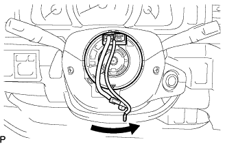 |
Rotate the spiral cable with steering sensor counterclockwise slowly by hand until it feels firm.
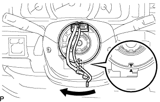 |
Rotate the spiral cable with steering sensor clockwise approximately 2.5 turns to align the marks.
| 34. INSTALL STEERING WHEEL ASSEMBLY |
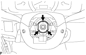 |
w/o AIRBAG:
Position the horn contact plate so that the projecting parts are as shown the illustration.
Align the matchmarks on the steering wheel assembly and the steering column assembly.
Install the nut.
Connect the connectors.
| 35. INSTALL HORN BUTTON ASSEMBLY |
Support the steering pad with one hand.
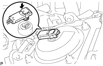 |
Connect the connector to the steering pad.
Connect the horn connector.
Confirm that the circumference groove of the "torx" screw fits in the screw case, and place the steering pad onto the steering wheel assembly.
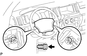 |
Using a "torx" socket wrench (T30), tighten the 2 "torx" screws.
| 36. INSTALL STEERING WHEEL COVER LOWER NO.3 |
| 37. INSTALL STEERING WHEEL COVER LOWER NO.2 |
| 38. CONNECT BATTERY NEGATIVE TERMINAL |
| 39. INSPECT HORN BUTTON ASSEMBLY |
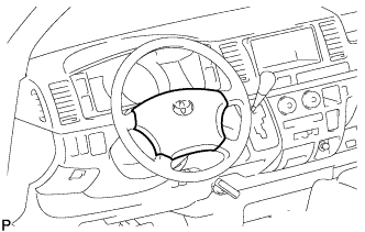 |
With the steering pad installed on the vehicle, perform a visual check. If there are any defects as mentioned below, replace the steering pad with a new one:
Make sure that the horn sounds.
| 40. INSPECT SRS WARNING LIGHT |