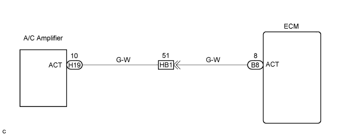
ECD SYSTEM > Air Conditioning Cut Control Circuit |
| 1.READ VALUE OF INTELLIGENT TESTER (CHECK OPERATION AIR CONDITIONER CUT CONTROL) |
Connect the intelligent tester to the DLC3.
Start the engine and air conditioning switch on.
Select the item "Powertrain/Engine and ECT/Active Test/Control the A/C cut signal" and read its value displayed on the intelligent tester.
Check operation of A/C magnetic clutch cut when air conditioning cut control is operated by the intelligent tester.
|
| ||||
| OK | ||
 | ||
| ||
| 2.INSPECT ECM (CHECK VOLTAGE) |
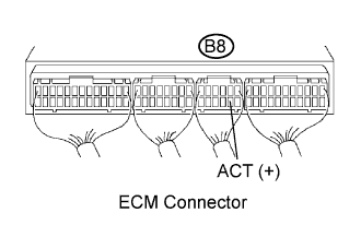 |
Start the engine.
Measure the voltage according to the value(s) in the table below.
| Tester Connection | Condition | Specified Condition |
| ACT (B8-8) - Body ground | Engine at idling | 9 to 14 V |
| ACT (B8-8) - Body ground | IG ON, Engine stop | 0 to 3 V |
|
| ||||
| OK | ||
| ||
| ||
| 3.CHECK HARNESS AND CONNECTOR (ECM - AIR CONDITIONER AMPLIFIER) |
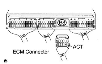 |
Disconnect the A/C amplifier H19 connector.
Disconnect the ECM B8 connector.
Measure the resistance according to the value(s) in the table below.
| Tester Connection | Specified Condition |
| ACT (H19-10) (*1) - ACT (B8-8) | Below 1 Ω |
| Tester Connection | Specified Condition |
| ACT (B8-8) - Body ground | 10 kΩ or higher |
|
| ||||
| OK | ||
| ||
| ||
| 1.INSPECT ECM (CHECK VOLTAGE) |
|
Start the engine.
Measure the voltage according to the value(s) in the table below.
| Tester Connection | Condition | Specified Condition |
| ACT (B8-8) - Body ground | Engine at idling | 9 to 14 V |
| ACT (B8-8) - Body ground | IG ON, Engine stop | 0 to 3 V |
|
| ||||
| OK | ||
| ||
| ||
| 2.CHECK HARNESS AND CONNECTOR (ECM - AIR CONDITIONER AMPLIFIER) |
|
Disconnect the A/C amplifier H19 connector.
Disconnect the ECM B8 connector.
Measure the resistance according to the value(s) in the table below.
| Tester Connection | Specified Condition |
| ACT (H19-10) (*1) - ACT (B8-8) | Below 1 Ω |
| Tester Connection | Specified Condition |
| ACT (B8-8) - Body ground | 10 kΩ or higher |
|
| ||||
| OK | ||
| ||
| ||

