OIL PUMP > INSTALLATION |
| 1. INSTALL TIMING GEAR CASE SUB-ASSEMBLY |
Place a new gasket on the cylinder block.
Install the timing gear case with the 5 bolts.
| 2. INSTALL OIL STRAINER SUB-ASSEMBLY |
Install a new gasket and oil strainer with the 2 bolts and 2 nuts.
| 3. INSTALL OIL PAN SUB-ASSEMBLY |
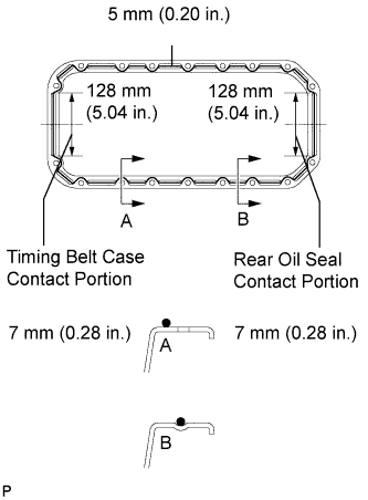
Remove any old packing (FIPG) material and do not drop any oil on the contact surfaces of the oil pan and cylinder block
![]() |
Apply seal packing to the oil pan as shown in the illustration.
Install the oil pan with the 16 bolts and 2 nuts. Uniformly tighten the bolts and nuts in several steps.
| 4. INSTALL TIMING BELT IDLER SUB-ASSEMBLY NO.2 |
Install the spacer and timing belt idler No.2 with the bolt.
Check that the timing belt idler sub-assembly No.2 moves smoothly.
| 5. INSTALL TIMING BELT IDLER SUB-ASSEMBLY NO.1 |
![]() |
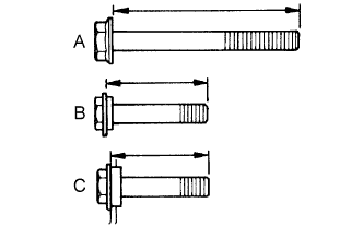
Inspect the 3 bolts.
![]() |
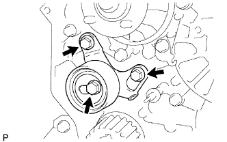
Install the timing belt idler No.1 with the 3 bolts.
| 6. INSTALL CRANKSHAFT TIMING PULLEY |
![]() |
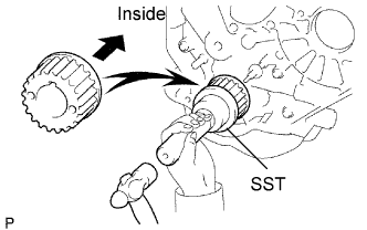
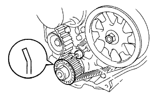
Align the pulley set key with the key groove of the timing pulley.
Using SST and a hammer, tap in the timing pulley with the flange side facing inward.
| 7. INSTALL WATER PUMP ASSEMBLY |
Install a new gasket, the water pump and tension spring bracket with the 6 bolts.
| 8. INSTALL TIMING BELT NO.2 COVER |
Install the timing belt cover with the 4 bolts.
| 9. INSTALL CAMSHAFT TIMING PULLEY |
![]() |
Install the woodruff key to the key groove of the camshaft.
Align the pulley set key with the timing mark outward.
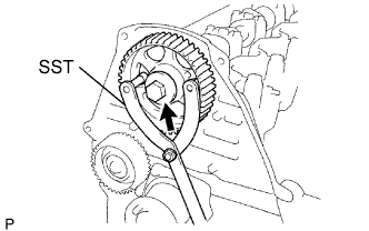
Using SST, install the pulley with the bolt.
| 10. INSTALL INJECTION PUMP |
![]() |
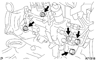
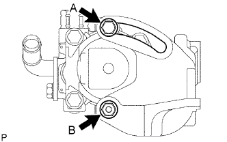
Install the injection or supply pump assembly to timing gear case, and temporarily tighten the 2 nuts.
Install injection pump stay No.1 to the injection or supply pump assembly rear end, and temporarily tighten the 3 bolts.
![]() |
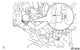
Rotate the pump body to make the marking of pump flange conform to the making of timing of gear case.
Tighten the 2 nuts to install the injection or supply pump assembly.
Tighten the 3 bolts to install the injection pump stay No.1.
Connect the 3 fuel hoses.
Connect the engine speed sensor connector.
Connect the spill control valve connector.
Connect the correction unit connector.
Connect the timer control valve connector.
Connect the fuel temperature sensor connector.
Connect the engine wire clamp.
| 11. SET NO.1 CYLINDER TO TDC/COMPRESSION |
![]() |
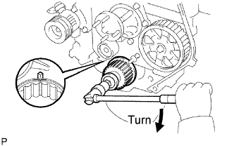
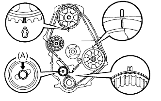
Using the crankshaft pulley bolt, align its groove with the timing pointer by turning the crankshaft clockwise.
![]() |
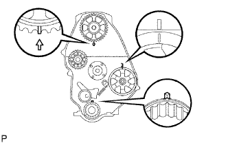
Set the timing and drive pulleys at each position.
| 12. INSTALL TIMING BELT |
![]() |
Remove any oil or water on each pulleys, and keep them clean.
Install the timing belt on the crankshaft timing and timing belt idlers.
![]() |
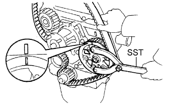
Using SST, slightly turn the injection pump drive pulley clockwise. Hang the timing belt on the pulley, and align the timing marks of the drive pulley and timing belt case.
![]() |
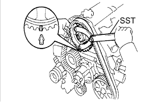
Using SST, slightly turn the camshaft timing pulley clockwise. Hang the timing belt on the timing pulley, and align the timing marks of the timing pulley and timing belt case.
Check that the timing belt has tension between the injection pump drive and camshaft timing pulleys.
Install the timing belt on the timing belt idler No.2.
| 13. CHECK VALVE TIMING |
![]() |
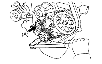
Loosen the timing belt idler No.1 bolt (A), and stretch the timing belt.
Slowly turn the crankshaft pulley 2 revolutions from TDC to TDC.
![]() |
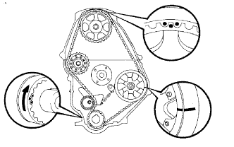
Check each pulley aligns with the timing marks as shown in the illustration.
If the timing marks do not align, remove the timing belt and reinstall it.
Tighten the timing belt idler No.1 bolt (A).
| 14. INSTALL TIMING BELT GUIDE |
![]() |
Install the belt guide with the cup side facing outward.
| 15. INSTALL TIMING CHAIN OR BELT COVER SUB-ASSEMBLY |
Remove the 2 nuts and wire harness clamp bracket.
![]() |
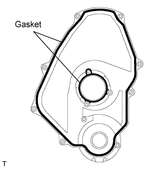
Install the 2 gaskets to the timing belt cover.
![]() |
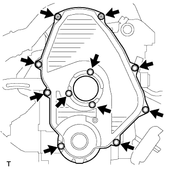
Install the timing belt cover with the 11 bolts.
Install the 2 nuts and wire harness clamp bracket.
| 16. INSTALL CRANKSHAFT PULLEY |
![]() |
Align the pulley set key with the key groove of the timing pulley.
Using SST and a hammer, tap in the timing pulley with the flange side facing inward.
| 17. INSTALL VANE PUMP DRIVE PULLEY |
![]() |
w/o Air conditioning:
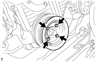
Install the vane pump drive pulley and vane pump pulley spacer with the 4 bolts.
w/ Air conditioning:
Install the 2 vane pump drive pulleys with the 4 bolts.
| 18. INSTALL COMPRESSOR MOUNTING BRACKET (w/ Air Conditioning) |
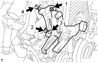
Temporarily install the compressor mounting bracket with the 4 bolts.
![]() |
Using several steps, uniformly install and tighten the 4 bolts in the sequence shown in the illustration.
![]() |
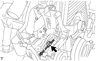
Temporarily tighten the bolt and spacer.
![]() |
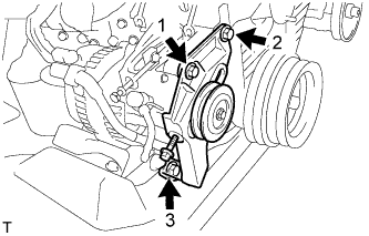
Temporarily install the compressor mounting bracket with the 3 bolts.
Using several steps, uniformly install and tighten the 3 bolts in the sequence shown in the illustration.
| 19. INSTALL COMPRESSOR AND MAGNETIC CLUTCH (w/ Air Conditioning) |
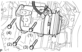
![]() |
Install the compressor and magnetic clutch with the 4 bolts.
| 20. INSTALL INJECTION PIPE SET |
Connect the 2 lower clamps on the intake manifold.
Install the 4 injection pipes.
Secure the injection pipes with the 2 upper pipe clamps and 2 nuts.
| 21. INSTALL VENTURI ASSEMBLY |
Install a new gasket and venturi.
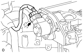
![]() |
Connect the throttle control motor connector.
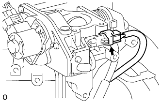
![]() |
Connect the throttle open switch connector.
| 22. INSTALL INTAKE AIR CONNECTOR BRACKET |
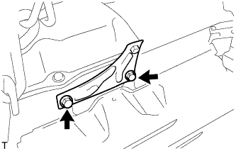
![]() |
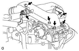
Install the 2 bolts and intake air connector bracket.
| 23. INSTALL INTAKE AIR CONNECTOR SUB-ASSEMBLY |
![]() |
Install a new gasket and intake air connector with the bolt and 3 nuts.
Connect the turbo pressure sensor connector.
Connect the ventilation hose.
| 24. INSTALL WATER PUMP PULLEY |
| 25. INSTALL FAN AND GENERATOR V BELT (w/o Air Conditioning) |
![]() |
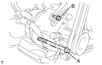
Install the V belt.
Using a bar, adjust the tension of the V belt.
Tighten the bolts A and B.
Check the tension of the V belt. (Click here)
| 26. INSTALL FAN AND GENERATOR V BELT (w/ Air Conditioning) |
![]() |
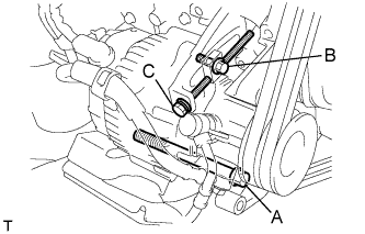
Install the V belt.
Tightening the bolt C, adjust the tension of the V belt.
Tighten the bolts A and B.
Check the tension of the V belt. (Click here)
| 27. INSTALL V (COOLER COMPRESSOR TO CRANKSHAFT PULLEY) BELT NO.1 (w/ Air Conditioning) |
![]() |
Install the V belt.
Tightening the bolt B, adjust the tension of the V belt.
Tighten nut A.
Check the tension of the V belt. (Click here)
| 28. INSTALL VANE PUMP V BELT |
![]() |
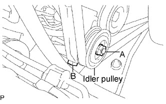
Install the V belt.
Using a bar, adjust the tension of the V-ribbed belt.
Tighten the bolt A and nut B.
Check the tension of the V belt. (Click here)
| 29. BLEED INJECTION PIPE |
Move the priming pump in the upper part of the fuel filter assembly up and down, and fill the injection pump assembly and fuel system with fuel.
Loosen one of the union nuts (in the nozzle side).
Crank the engine until fuel comes out from the union nut (in the nozzle side).
Tighten the union nut.
The above operation should be carried out each injection pipe.
| 30. CONNECT WATER HOSE (for Heater) |
| 31. INSTALL RADIATOR HOSE NO.4 |
| 32. INSTALL RADIATOR HOSE INLET |
| 33. ADD ENGINE COOLANT |
Close the engine drain plug.
Close the radiator drain cock plug.
Slowly fill the cooling system with coolant.
Slowly pour coolant into the radiator reserve tank until it reaches the FULL line.
Install the radiator cap to the radiator reserve tank.
Press the inlet and outlet radiator hoses several times by hand while warming up the engine.
Stop the engine, and wait until the engine coolant cools down.
Add coolant to the FULL line of the radiator reservoir.
| 34. ADD ENGINE OIL |
| 35. CHECK FOR ENGINE OIL LEAKS |
| 36. CHECK FOR ENGINE COOLANT LEAKS |
Fill the radiator with coolant and attach a radiator cap tester to the radiator.
Warm up the engine.
Using a radiator cap tester, increase the pressure inside the radiator to 118 kPa (1.2 kgf/cm2, 17.1 psi), and check that the pressure does not drop.
| 37. CHECK FOR FUEL LEAKS |
Check that there are no fuel leaks anywhere on the fuel system after doing maintenance.
| 38. INSTALL ENGINE SERVICE HOLE SUB COVER SUB-ASSEMBLY |
Install the 5 bolts and engine service hole cover.
| 39. INSTALL FRONT DOOR SCUFF PLATE RH |
| 40. INSTALL FRONT SEAT ASSEMBLY RH |
![]() |
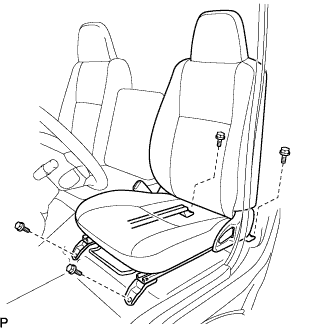
Connect the front seat inner belt assembly connector and install the front seat assembly.
Align the front seat assembly adjuster pin with the holes in the body.
Move the front seat assembly to the rearmost position.
Temporarily tighten the 2 bolts on the front side of the front seat assembly.
Move the front seat assembly fully forward.
Temporarily tighten the 2 bolts on the rear side of the front seat assembly.
Move the front seat assembly to the rearmost position.
Fully tighten the 2 bolts on the front side of the front seat assembly in the order of outer and inner side.
Move the front seat assembly fully forward.
Fully tighten the 2 bolts on the rear side of the front seat assembly in the order of outer and inner side.